
8-bit Arithmetic and Logic Unit (ALU)
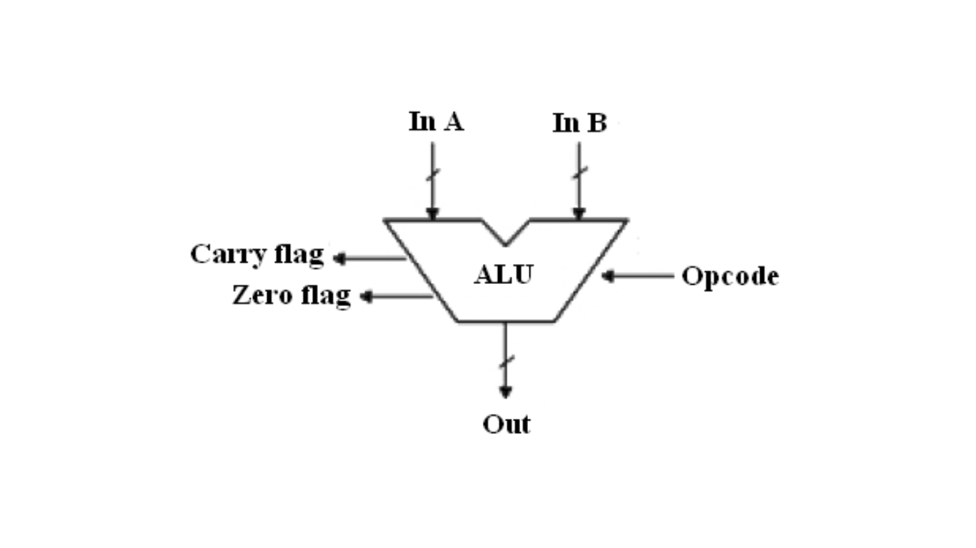
The 8-bit Arithmetic and Logic Unit (ALU) is a fundamental building block of a processor responsible for performing arithmetic and logic operations. The ALU takes two 8-bit operands (Operand1 and Operand2) and an opcode (Opcode) as inputs. The opcode selects the operation to be performed on the operands. The result of the operation is provided through the 16-bit Result port. Additionally, there are two flags flagC and flagZ, which indicate the carry-out and zero result conditions, respectively.
The Arithmetic Unit compromises three functions. They are:
- Addition
- Subtraction
- Multiplication
The Logical Unit compromises five functions. They are:
- Bitwise AND
- Bitwise OR
- Bitwise NAND
- Bitwise NOR
- Bitwise XOR
Flags
ALU updates the conditional flags, which are used by the processor to perform other operations like condition checking and branching. In this example, two flags are implemented. They are:
- Zero – If all the bits of the result data are zero then the zero flag is set
- Carry out – If the addition of the two operands gives the carry out this flag is set
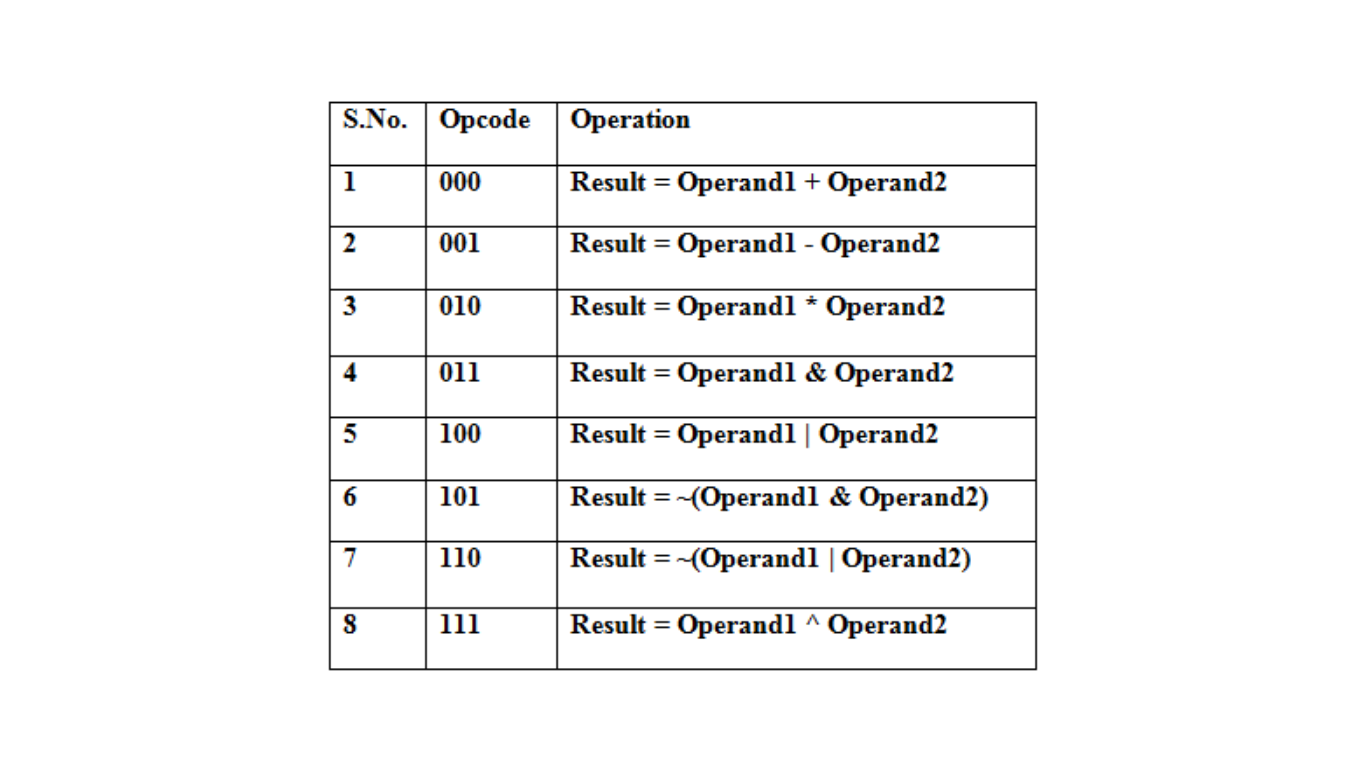
Truth Table
Figure 2 shows the truth table of the 8-bit ALU. The ALU works on 8-bit operands. It supports 8 instructions which are selected by the 3-bit Opcode.
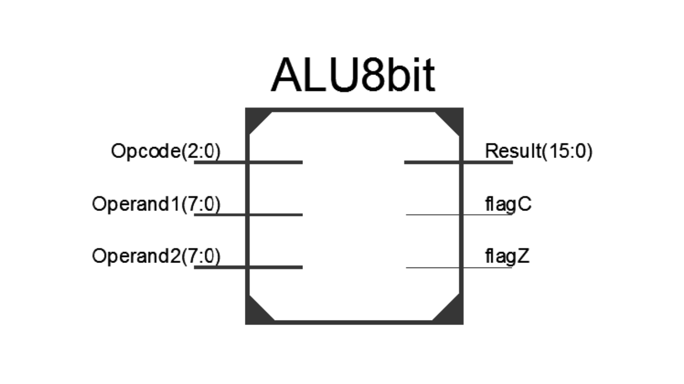
Verilog Module: 8-bit ALU
The Verilog module of the 8-bit ALU is shown below. It implements the arithmetic functions of addition, subtraction, and multiplication, as well as the logical functions of bitwise AND, OR, NAND, NOR, and XOR.
Verilog Code for the 8-bit ALU
module ALU8bit(
input [2:0] Opcode,
input [7:0] Operand1,
input [7:0] Operand2,
output reg [15:0] Result = 16’b0,
output reg flagC = 1’b0,
output reg flagZ = 1’b0
);
parameter [2:0] ADD = 3’b000,
SUB = 3’b001,
MUL = 3’b010,
AND = 3’b011,
OR = 3’b100,
NAND = 3’b101,
NOR = 3’b110,
XOR = 3’b111;
always @ (Opcode or Operand1 or Operand2)
begin
case (Opcode)
ADD: begin
Result = Operand1 + Operand2;
flagC = Result[8];
flagZ = (Result == 16’b0);
end
SUB: begin
Result = Operand1 – Operand2;
flagC = Result[8];
flagZ = (Result == 16’b0);
end
MUL: begin
Result = Operand1 * Operand2;
flagZ = (Result == 16’b0);
end
AND: begin
Result = Operand1 & Operand2;
flagZ = (Result == 16’b0);
end
OR: begin
Result = Operand1 | Operand2;
flagZ = (Result == 16’b0);
end
NAND: begin
Result = ~(Operand1 & Operand2);
flagZ = (Result == 16’b0);
end
NOR: begin
Result = ~(Operand1 | Operand2);
flagZ = (Result == 16’b0);
end
XOR: begin
Result = Operand1 ^ Operand2;
flagZ = (Result == 16’b0);
end
default: begin
Result = 16’b0;
flagC = 1’b0;
flagZ = 1’b0;
end
endcase
end
endmodule
Verilog Test Bench for 8-bit ALU
The Verilog test bench for the 8-bit ALU is shown below. It checks the functionality of the ALU by providing stimulus to the input ports (Opcode, Operand1, and Operand2) and observing the output ports (Result, flagC, and flagZ).
module ALU8bit_tb;
// Inputs
reg [2:0] Opcode;
reg [7:0] Operand1;
reg [7:0] Operand2;

// Outputs
wire [15:0] Result;
wire flagC;
wire flagZ;

// Temporary variable
reg [2:0] count = 3'd0;

// Instantiate the Unit Under Test (UUT)
ALU8bit uut (
.Opcode(Opcode),
.Operand1(Operand1),
.Operand2(Operand2),
.Result(Result),
.flagC(flagC),
.flagZ(flagZ)
);

initial begin
// Initialize Inputs
Opcode = 3'b0;
Operand1 = 8'd0;
Operand2 = 8'd0;

// Wait 100 ns for global reset to finish
#100;

// Add stimulus here
Operand1 = 8'hAA;
Operand2 = 8'h55;

for (count = 0; count < 8; count = count + 1'b1) begin
Opcode = count;
#20;
end
end
endmodule
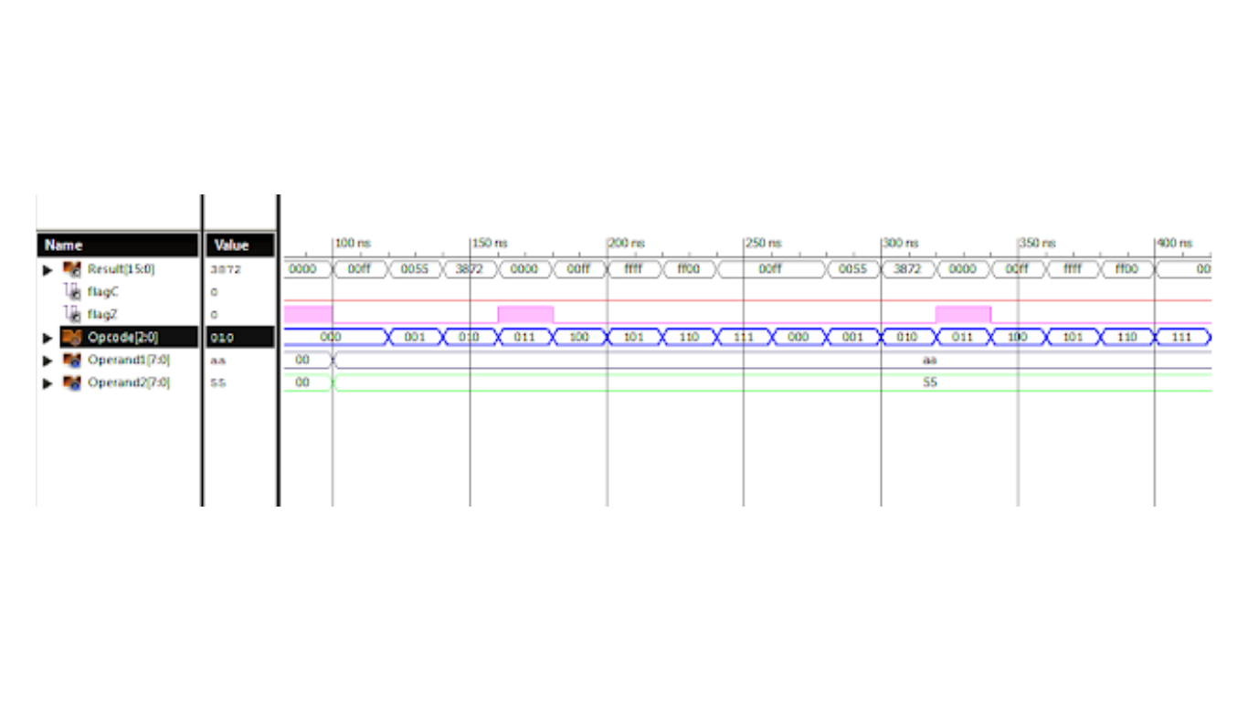
Timing Diagram for 8-bit ALU
The following figure presents the timing diagram of the 8-bit ALU, illustrating the waveforms of the output Result, flagC, and flagZ as different operations are performed with different operand values.
The provided Verilog module and test bench ensure the correct functionality of the 8-bit ALU for various arithmetic and logical operations.