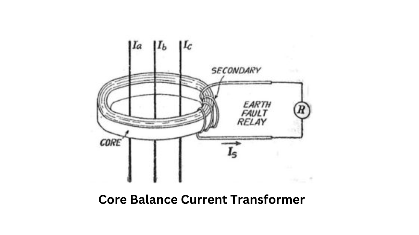
Core Balance Current Transformer
We use the CBCT because it lets us pass these cables through its center, allowing for effective monitoring of the current.

Core Balance Current Transformers are usually placed directly on a cable near the cable gland of the switchgear. If cables are already installed in the switchgear, physically split cores, which are also known as Slip-over type CTs, are used.
Working Principle of CBCT
The working principle of CBCT revolves around the connection between the secondary of a CBCT and an Earth Fault Relay. Under normal operating conditions, the three-phase currents, represented as Īa + Īb + Īc = 0, result in zero residual currents in the primary. The residual current refers to the zero sequence current, which means that no flux is developed in the CBCT core. Consequently, there is no current in the secondary circuit.
Let’s delve into the working principle of CBCT in more detail. Consider Īa, Īb, and Īc as the three line currents and Φa, Φb, and Φc as their corresponding magnetic flux components in the core. Assuming that the CT operates within the linear region, described by the B-H Curve, the magnetic flux caused by each phase current is directly proportional to the phase current. Therefore, we express it as follows:
- Φa = kIa
- Φb = kIb
- Φc = kIc
Here, “k” represents the constant of proportionality. It’s important to note that the same constant of proportionality applies since all three phase currents produce magnetic flux in the same magnetic core.
Consequently, we can express the resultant magnetic flux in the CBCT core as:
Φr = k(Īa + Īb + Īc) …………………..(1)
Based on the theory of symmetrical components, we know that:
Īa + Īb + Īc = 3Ī0 = Īn
Here, Io represents the zero sequence current, and In represents the neutral current. Hence, we can rewrite equation (1) as:
Φr = kĪn …………………………(2)
Now, let’s consider two cases:
Case 1: Normal Condition
When Īa + Īb + Īc = 0, equation (1) informs us that the net resultant flux in the CBCT core, Φr, equals 0. Consequently, there is no secondary current, and as a result, the Earth Fault Relay remains inactive.
Case 2: Earth Fault
During an earth fault, the three-phase current passing through the center of the Core Balance Current Transformer is unbalanced, resulting in a zero sequence current flow. For instance, in the case of a single-line ground fault, the equation becomes:
If = 3Ia0 = In
As a consequence, equation (2) informs us that the net magnetic flux in the CBCT core, Φr, will have a finite value, which in turn induces a current in the secondary circuit, activating the earth fault relay. This is the reason why a Core Balance Current Transformer or CBCT is also known as a Zero Sequence Current Transformer.
Advantages of Core Balance Current Transformer
The utilization of CBCT for earth fault protection offers several advantages over conventional systems:
Single CT Core Usage
Unlike conventional systems that require three CT cores with their secondary windings connected residually, CBCT utilizes only one CT core. This reduces the magnetizing current necessary to produce a specific secondary current by one-third, thereby significantly enhancing the sensitivity of the protection system.
Flexible Secondary Turn Selection
Since no secondary current flows under normal operating conditions due to the balanced currents, the number of secondary turns does not need to be related to the cable’s rated current. This flexibility allows the selection of the number of secondary turns to optimize the effective primary pick-up current.
Mounting and Application
In conclusion, Core Balance Current Transformers are extremely important for improving earth fault protection in low and medium-voltage systems. By using just one CT core, these transformers enhance sensitivity and allow for a flexible selection of secondary turns, which is highly beneficial in electrical installations.
Always remember to prioritize safety and protection in electrical systems, and Core Balance Current Transformers play a significant role in achieving these objectives.