
Voltage regulators play a important role in maintaining a constant voltage at the output of electronic circuits. They ensure that the output voltage remains within the desired limits, regardless of variations in input voltage or load current. In this article, we will explore the differences between two types of voltage regulators: Shunt and Series voltage regulators.
What is a Voltage Regulator?
A voltage regulator is an electronic device that transforms an unregulated DC power supply into a regulated DC supply, with minimal variations in the output voltage. It is also referred to as a control element. There are two main types of voltage regulators based on the arrangement or placement of the control element: Shunt and Series voltage regulators.
What is a Shunt Voltage Regulator?
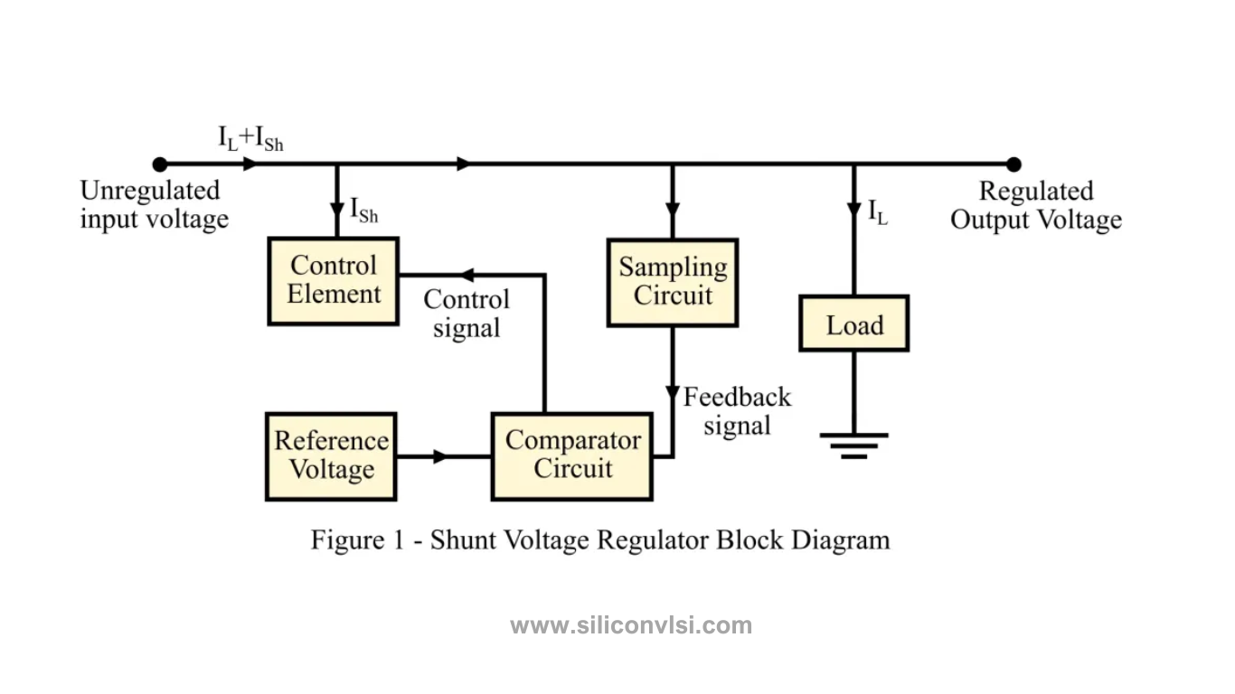
Shunt Voltage Regulator Block DiagramA shunt voltage regulator is connected in parallel with the load in an electronic circuit. As depicted in Figure 1, the input voltage splits into the shunt voltage regulator (control element), and the remaining current flows to the load. The shunt current (Ish) is responsible for maintaining a constant and stable output voltage.
The circuit consists of a sampling circuit and a comparator circuit. The sampling circuit generates a feedback signal, which is compared to the applied input reference voltage by the comparator circuit. The difference between these signals produces a control signal, indicating the amount of current needed to maintain a constant output voltage at the load.
What is a Series Voltage Regulator?
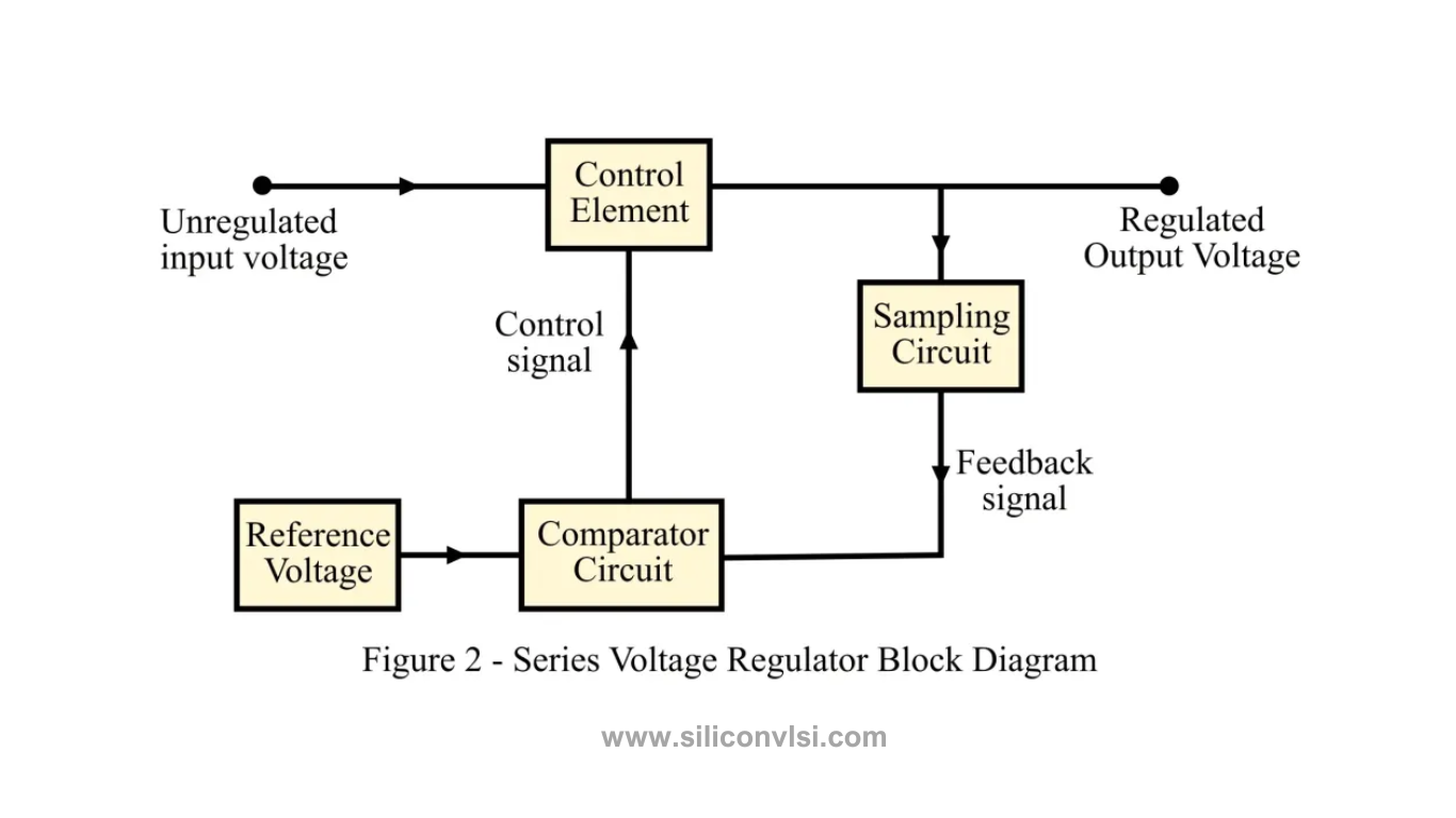
In a series voltage regulator, the control element is connected in series with the load at the output, as shown in Figure 2. The series voltage regulator regulates the amount of input voltage reaching the load.
Similar to the shunt voltage regulator, the series voltage regulator also employs a sampling circuit and a comparator circuit. The comparator compares the feedback signal from the sampling circuit with the reference input voltage, generating a control signal. This control signal is then applied to the series voltage regulator element, ensuring a constant and regulated output voltage at the load.
Difference Between Shunt and Series Voltage Regulators
Below is a table highlighting the key differences between shunt and series voltage regulators:
| Parameter | Shunt Voltage Regulator | Series Voltage Regulator |
|---|---|---|
| Arrangement | Connected in parallel to the load in an electronic circuit | Placed in series with the load in an electronic circuit |
| Regulation of Output Voltage | Poorly regulated output voltage | Highly regulated output voltage |
| Circuit Construction | Simple circuitry design | Complex circuitry design |
| Flow of Electric Current | Only a part of the total input current flows through | The entire input current flows through |
| Usage | Applications with constant voltage requirements | Applications with both constant and varying voltage operations |
| Balance in Variation in Output Voltage | Adjusting current flowing across the regulator | Adjusting voltage across the regulator |
| Efficacy | Efficiency depends on the amount of load current available | Efficiency depends on the amount of output voltage available |
| Current and Voltage Ratings | Low current-rated and high voltage-rated device | Low voltage-rated and high current-rated device |
| Examples | Zener voltage regulator | Series feedback regulator |
Conclusion
In conclusion, both shunt and series voltage regulators ensure a steady output voltage in electronic circuits. The significant difference lies in their connection to the load, with shunt regulators being parallel and series regulators being in series. Although voltage regulators stabilize the output voltage, they may introduce certain instabilities in circuit operations. Understanding the distinctions between shunt