
First-In-First-Out Buffer (FIFO Buffer) – Simplified Explanation
FIFO stands for “First In First Out,” which simply means that the data that arrives first will also be the first to leave. Imagine a line of people waiting to get on a bus. The person who arrives first gets on the bus first. A FIFO Buffer is like a digital queue that stores data in the order it arrives and retrieves it in the same order. This concept is commonly used in computer hardware for synchronization.
FIFO Buffer Basics: A FIFO Buffer works like a memory area that holds data. It’s organized in a way that the first data in is the first to come out. It’s often implemented as a circular queue, and it has two important pointers:
Read Pointer/Read Address Register: Points to the data that is ready to be read.
Write Pointer/Write Address Register: Points to the location where new data will be written.
Initially, both pointers are at the first memory location, which indicates an empty FIFO. When the difference between the read and write pointers equals the size of the memory, the FIFO is full.
Synchronous FIFO In a synchronous FIFO, data is written and read using the same clock signal. This means that data enters and exits the FIFO in a synchronized manner. Imagine people entering and leaving a room through the same door, taking turns.
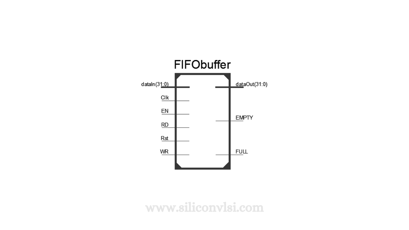
Verilog Module – FIFO Buffer
Think of this like a module in a digital circuit that follows the FIFO principle. It can store eight sets of 32-bit data. It has inputs for adding data (dataIn), clock (Clk), and signals to control reading and writing (RD, WR). It also has outputs for getting data out (dataOut), and signals that tell you if it’s empty (EMPTY) or full (FULL).
Verilog Code – FIFO Buffer
This is like telling the module how to work. It defines what happens when you put data in, take data out, and other operations. It’s written in a specific language that the module understands.
// Module for FIFO Buffer
module FIFObuffer(
input Clk,
input RD,
input WR,
input EN,
input Rst,
input [31:0] dataIn,
output [31:0] dataOut, // Internal registers
output reg EMPTY,
output reg FULL
);
reg [2:0] Count = 0;
reg [31:0] FIFO [0:7];
reg [2:0] readCounter = 0,
writeCounter = 0;
assign EMPTY = (Count == 0) ? 1’b1 : 1’b0;
assign FULL = (Count == 8) ? 1’b1 : 1’b0;
always @(posedge Clk)
begin
if (EN == 0);
else
begin
if (Rst)
begin
readCounter = 0;
writeCounter = 0;
end
else if (RD == 1’b1 && Count != 0)
begin
dataOut = FIFO[readCounter];
readCounter = readCounter + 1;
end
else if (WR == 1’b1 && Count < 8)
begin
FIFO[writeCounter] = dataIn;
writeCounter = writeCounter + 1;
end
else;
end
if (writeCounter == 8)
writeCounter = 0;
else if (readCounter == 8)
readCounter = 0;
else;
if (readCounter > writeCounter)
begin
Count = readCounter – writeCounter;
end
else if (writeCounter > readCounter)
begin
Count = writeCounter – readCounter;
end
else;
end
endmodule
Verilog Test Bench – FIFO Buffer
This is like testing the module to ensure it functions correctly. You provide inputs and observe outputs to see if it behaves as expected.
// Verilog Test Bench for FIFO Buffer
`timescale 1ns / 1ps
module FIFObuffer_tb;
// Inputs
reg Clk;
reg [31:0] dataIn;
reg RD;
reg WR;
reg EN;
reg Rst;
// Outputs
wire [31:0] dataOut;
wire EMPTY;
wire FULL;
// Instantiate the Unit Under Test (UUT)
FIFObuffer uut (
.Clk(Clk),
.dataIn(dataIn),
.RD(RD),
.WR(WR),
.EN(EN),
.dataOut(dataOut),
.Rst(Rst),
.EMPTY(EMPTY),
.FULL(FULL)
);
initial begin
// Initialize Inputs
Clk = 1’b0;
dataIn = 32’h0;
RD = 1’b0;
WR = 1’b0;
EN = 1’b0;
Rst = 1’b1;
// Wait 100 ns for global reset to finish
#100;
// Add stimulus here
EN = 1’b1;
Rst = 1’b1;
#20;
Rst = 1’b0;
WR = 1’b1;
dataIn = 32’h0;
#20;
dataIn = 32’h1;
#20;
dataIn = 32’h2;
#20;
dataIn = 32’h3;
#20;
dataIn = 32’h4;
#20;
WR = 1’b0;
RD = 1’b1;
end
always #10 Clk = ~Clk;
endmodule
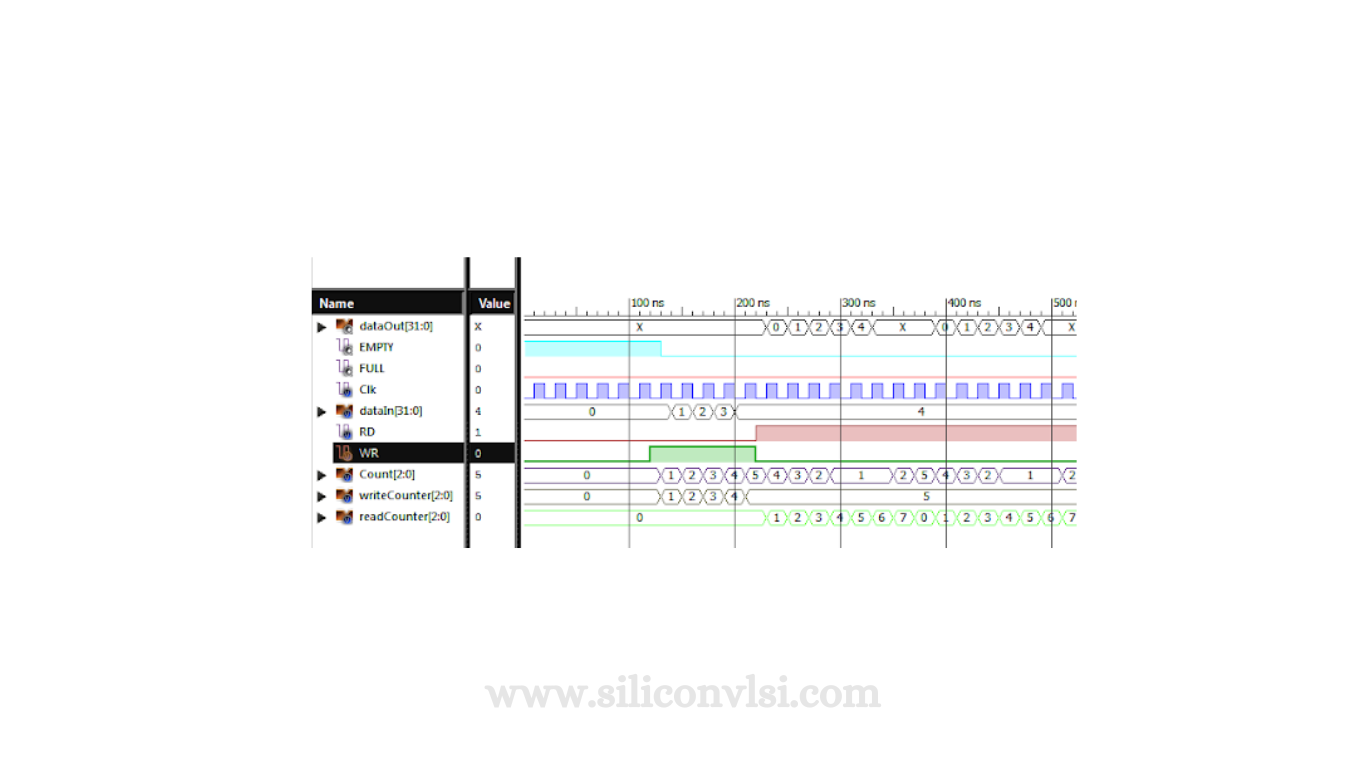
Timing Diagram
This is a visual representation that shows when events occur. It helps you understand the sequence of actions in the module.
In a nutshell, a First-In-First-Out Buffer, or FIFO Buffer, is a digital mechanism that manages data in the order it arrives, allowing synchronized reading and writing. It’s like a digital queue where the first data in is the first to come out.