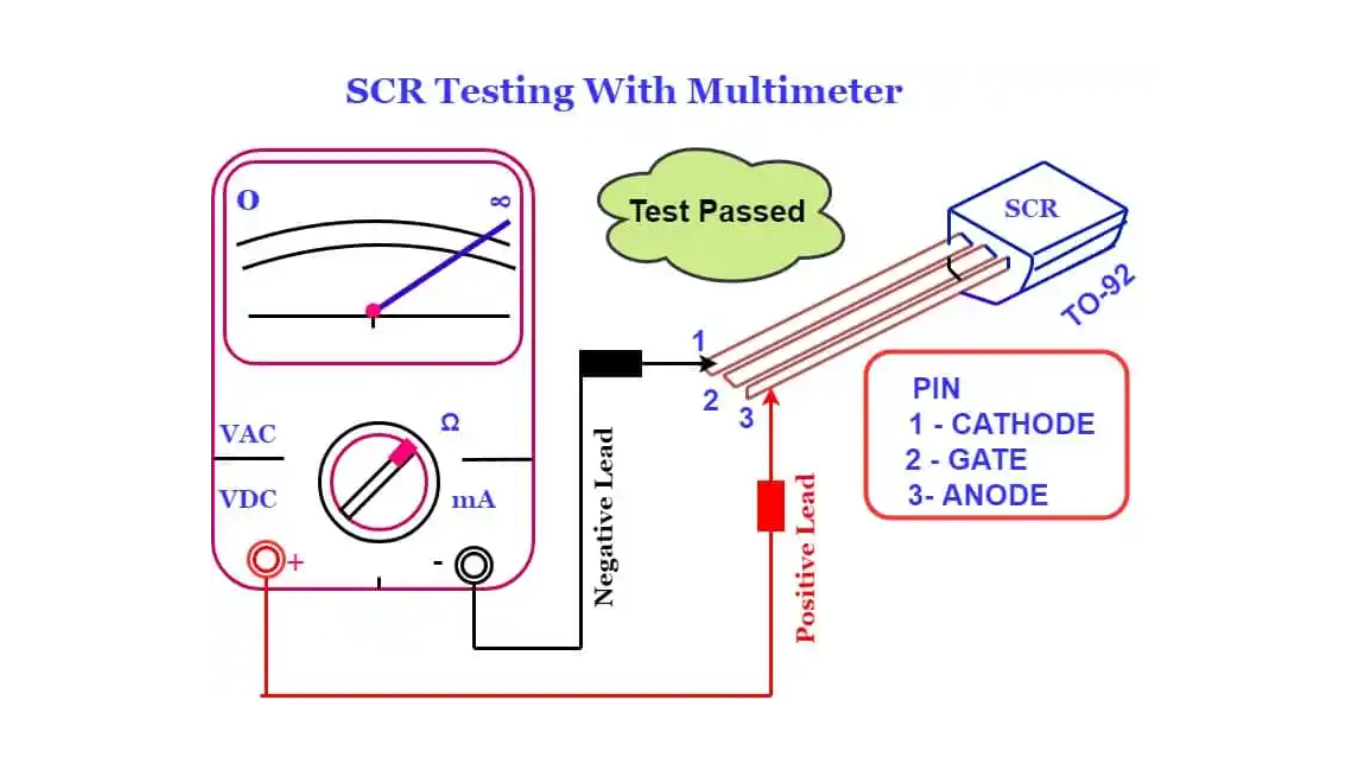
How to Test an SCR Using a Multimeter: Step-by-Step Guide
SCR (Silicon-Controlled Rectifier) is a semiconductor device widely used in various electronic applications, including power control and switching circuits. Testing an SCR using a multimeter is a straightforward process that helps determine if the device is functioning properly. This article provides a step-by-step guide on how to test an SCR using a multimeter, ensuring accurate results and effective troubleshooting.
Before diving into the testing procedure, it’s important to understand the basic structure and characteristics of an SCR. An SCR is a three-terminal semiconductor device with a control terminal (gate), an anode, and a cathode. It acts as a switch, allowing current flow from anode to cathode when triggered, and blocking current flow in the opposite direction.
Testing SCR with a Multimeter
To test an SCR using a multimeter, you will need the following tools and equipment:
Digital Multimeter: Use a digital multimeter capable of measuring resistance, voltage, and diode forward voltage drop.
Connecting Wires: Use suitable connecting wires to establish the necessary connections between the multimeter and the SCR.
Step-by-Step Procedure
Follow these steps to test an SCR using a multimeter:
Disconnect Power: Ensure that the circuit and power source connected to the SCR are disconnected to prevent any accidents during the testing process.
Set the Multimeter: Set the multimeter to the diode testing mode or the forward voltage drop mode, depending on the available options on your multimeter.
Identify the Terminals: Identify the gate, anode, and cathode terminals of the SCR. Refer to the datasheet or markings on the SCR for accurate identification.
Connect Multimeter to the SCR: Connect the positive (red) probe of the multimeter to the anode terminal of the SCR and the negative (black) probe to the cathode terminal.
Testing Forward Voltage Drop: Apply the multimeter probes to the anode and cathode terminals and observe the forward voltage drop reading on the multimeter display. The forward voltage drop across a conducting SCR is typically around 0.7 to 1.2 volts, depending on the device specifications.
Testing Gate Triggering Voltage: Connect the positive (red) probe of the multimeter to the gate terminal and the negative (black) probe to the cathode terminal. Apply a positive voltage pulse or signal to the gate terminal while observing the multimeter reading. The gate triggering voltage is specified in the SCR datasheet and should be within the expected range.

FAQs
Q1. Can an SCR be tested while it is in the circuit?
Yes, it is possible to test an SCR while it is in the circuit. However, it is recommended to disconnect the power source and any connected circuits to ensure accurate and safe testing.
Q2. What should be the forward voltage drop reading for a properly functioning SCR?
The forward voltage drop across a conducting SCR is typically around 0.7 to 1.2 volts, depending on the specific device. Consult the datasheet or specifications for the SCR being tested for precise values.
Q3. Can a multimeter damage the SCR during testing?
If the multimeter is used correctly and within its specified limits, it should not damage the SCR during testing. However, it is always advisable to exercise caution and follow proper testing procedures.
Q4. What should be the gate triggering voltage for a properly functioning SCR?
The gate-triggering voltage varies depending on the specific SCR model and specifications. Refer to the SCR datasheet or specifications to determine the expected range of gate-triggering voltage.
Q5. What if the SCR fails the multimeter test?
If the SCR fails the multimeter test, it indicates a potential issue with the device. Consider replacing the SCR with a new one and retesting to verify the results.