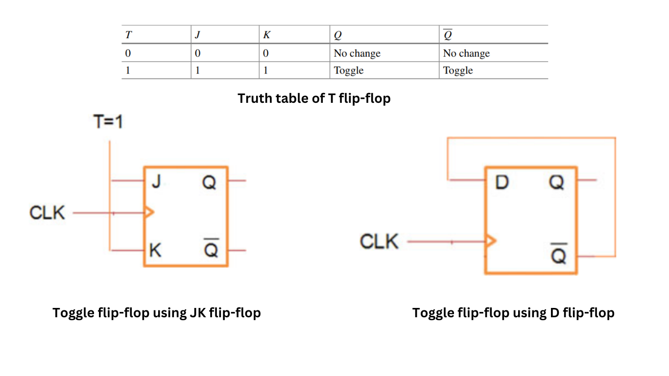
The Toggle flip-flop, also known as the T flip-flop or TFF, is a type of sequential logic circuit that has a unique characteristic. It toggles its output state based on the input signal. Here are some key points about the T flip-flop. The toggle flip-flop toggles on the active edge of the clock and can be designed using the JK flip-flop or D flip-flop.
Toggle flip-flop using JK flip-flop
Using JK flip-flop, tied J and K inputs to logic 1 to get the toggle output as shown in Figure 1. The truth table of toggle flip-flops designed using JK is shown in Table

Toggle flip-flop using D flip-flop
As described in the above table for T = 0 the flip-flop output maintains the previous output which is no change in the output Q and complement of Q. For T = 1 the flip-flop toggles on the rising edge of the clock. Using the D flip-flop, we can design the toggle flip-flop by feeding back the complement of Q to the D input. As shown in the above figure let us assume the output Q of the flip-flop is 0 and the complement of Q is Q = 1. As D = 1 on the rising edge of the clock the flip-flop samples logic 1. As output Q = 1, the complement of Q is 0 and fed back to D. On the next rising edge of the clock 0 is sampled. Thus, output Q of flip-flop toggles on every rising edge of the clock.
Application of T flip-flop
State Toggling: The T flip-flop is designed to toggle its output state (change from 0 to 1 or from 1 to 0) whenever a specific input condition is met. The input signal, commonly referred to as the toggle or T input, determines whether the output state should be toggled or remain the same.
Simplicity: The T flip-flop is one of the simplest types of flip-flops, consisting of just a few logic gates. It typically contains two inputs: the T input and a clock input (CLK). The T input controls the toggling behavior, while the clock input synchronizes the operation of the flip-flop.
Edge-Triggered Operation: The T flip-flop is edge-triggered, meaning its output state changes only on a specific transition of the clock signal. The transition can be either the rising edge (positive edge) or the falling edge (negative edge) of the clock signal, depending on the specific implementation.
Frequency Division: One of the practical uses of the T flip-flop is in frequency division circuits. By connecting the T input to the output of another flip-flop or by connecting it to a specific logic level, the T flip-flop can divide the frequency of the input signal by two.
Counting and Modulo-2 Arithmetic: T flip-flops can be cascaded together to create binary counters. Each flip-flop represents a binary bit, and the toggling behavior of the T flip-flop allows for counting or modulo-2 arithmetic operations.
Control Signal Generation: T flip-flops are often used to generate control signals in digital circuits. By connecting the T flip-flop’s output to the input of other components or logic gates, the output can be used to control the execution of specific operations or to synchronize the timing of various events.
Frequency Division Multiplexing: T flip-flops can be used in frequency division multiplexing (FDM) applications. By using multiple T flip-flops with different T input values and connecting their outputs to a common bus, it is possible to transmit multiple frequency signals over a single communication channel.