
Verilog Modules
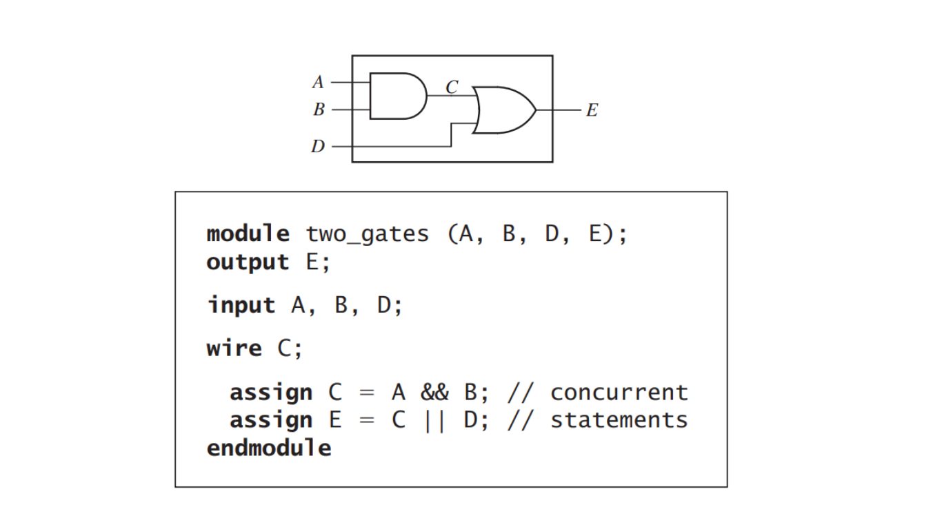
A module description is a Verilog code’s overall structure. A module is a fundamental building block that describes the input and output signals as well as how the module will function inside. As an illustration, think about Figure 1. The inputs and outputs are specified in the module declaration, which goes by the name two_gates. The three are output signals, while A and B are input signals. The module contains a declaration for the signal C. given that it is an internal signal, as a cable. The two parallel claims that characterize
The gates are set, and end module marks the module’s conclusion. Each and every input and output The module declaration lists signals without indicating whether they are input or output.
What is the basic building block in Verilog, and what does it include?
The basic building block in Verilog is a module, which includes declarations for input and output signals and specifies the internal operation of the module.
In a Verilog module, how are input and output signals declared, and what does it mean when they are listed without specifying their direction?
Input and output signals are declared in a Verilog module by listing their names. When they are listed without specifying their direction, they represent the external interface of the module, connecting it to the outside world.
What is the typical structure of a Verilog module declaration, and what parts are optional?
A Verilog module declaration typically consists of the module name, a list of interface signals, port declarations, and a functional specification. The items enclosed in square brackets, such as port declarations, are optional.
How are signal directions specified in Verilog, and what keywords are used for input, output, and bidirectional signals?
Signal directions in Verilog are specified using keywords. Input port signals are indicated by the keyword “input,” output port signals by “output,” and bidirectional signals by “inout.”
What is the purpose of the port declaration section in a Verilog module?
The port-declarations section is used to declare internal signals that are used within the module. These signals are not part of the external interface.