
Dielectric
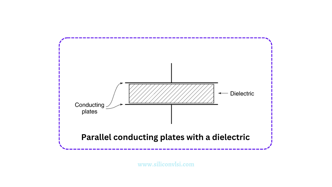
Two parallel conducting plates are separated by a dielectric, an insulating material commonly used in capacitors, such as Mylar, mica, or polypropylene. When a voltage (V) is applied between the plates, the work done to move a unit charge between them is equal to the applied voltage (V). The dielectric’s presence increases the charge on the conductors’ surfaces, resulting in an increased charge per unit voltage. The ratio of charge on the plates with and without the dielectric is known as the relative dielectric constant, denoted as “Epsilon R.” A higher dielectric constant indicates that more charge can be stored on the plates for a given voltage. Notably, the relative dielectric constant for air is 1.0.
When a dielectric is introduced into an existing E-field, the field strength in the dielectric is reduced. This reduction implies less field energy stored in the volume of space occupied by the dielectric. Importantly, the E-field discontinuity at the boundary of the dielectric does not imply the presence of charge on the dielectric surface.
In summary, dielectrics play an important role in capacitors, influencing the storage of charge and altering the electric field between conducting plates. The relative dielectric constant quantifies this influence, with higher values indicating increased charge storage efficiency. Understanding these principles is essential for designing and analyzing capacitor-based circuits in electronic systems.
Dielectric Materials Used in Capacitors
A capacitor’s dielectric material is selected according to its relative permittivity.The table below lists some typical dielectric materials used in capacitors.
| Dielectric Material | Relative Permittivity |
| Vacuum | 1 |
| Teflon | 2.1 |
| Polyethylene | 2.25 |
| Polypropylene | 2.2 – 2.36 |
| Polystyrene | 2.4 – 2.7 |
| Glass | 3.7 – 10 |
| Titanium dioxide | 86 – 173 |
| Mica | 5.6 – 8 |
| Paper | 3.85 |
| Tantalum oxide | 27.7 |
| Ceramic porcelain | 4.5 – 6.7 |