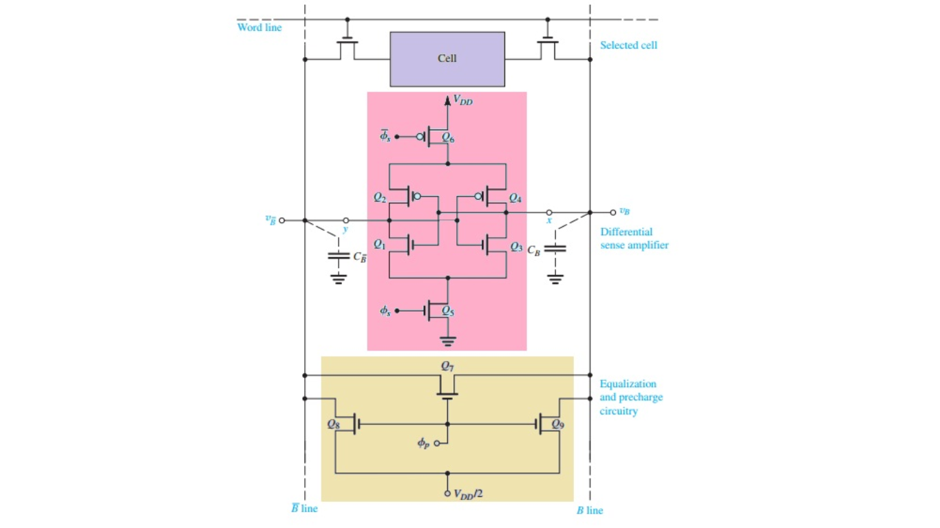
Sense amplifiers
Sense amplifiers play a major role in memory circuits and they provide performance speed-up while reducing power dissipation.
The sense amplifiers are used to detect the small voltage difference (approximately one-tenth of Vdd) in the bit lines resulting in reduced power dissipation without reduction in the overall performance.
The use of sense amplifiers has become even more critical in low voltage operation, because of bit lines’ low voltage level, static noise margin, and the propagation delay of the voltage amplifiers. The voltage difference is then amplified to the intended voltage level of logic 1 & 0. As shown in Figure, the popular structure of sense amplifiers in low-power design is the cross-coupled inverter latch, due to negligible static power dissipation.
The CMOS inverter latch has a high gain in the transient operation region, and the gain of the sense amplifier itself depends on the sizing of the inverters.
Precharge and evaluation phase circuits for sense amplifiers
The precharge and evaluation circuit for a memory sense amplifier consists of several transistors and control lines. Firstly, there is a first precharge-phase transistor with its source connected to a power-supply potential, its gate connected to a precharge control line, and its drain. Secondly, a second precharge-phase transistor is connected with its drain to the drain of the first precharge-phase transistor, its source, and its gate connected to the source through a feedback circuit. Thirdly, a first read-phase transistor has its source connected to the power-supply potential, and its gate and drain connected to a comparator. Fourthly, a second read-phase transistor is connected with its drain to the drain of the first read-phase transistor, its source connected to the source of the second precharge-phase transistor, and its gate connected to the source of the second read-phase transistor through a feedback circuit. Finally, a column decoder is connected to the sources of the second precharge-phase and second read-phase transistors.
Why do we need a precharge circuit?
During the reading operation, the precharge signal is pulled high, and either or BL & BL bar discharges. The respective bit lines will continue to discharge to a voltage small enough to be detected by the sense amplifier. Once the bit lines voltage falls within the sensing range, the sense enable is pulled high. The activation of the Sense enables the signal will discard the internal nodes’ voltage of the sense amplifier from the bit lines and allow the internal nodes to reach the rail-to-rail swing. A solution to increase sense amplifiers‘ performance is to increase the VDD level of the precharge circuit.
