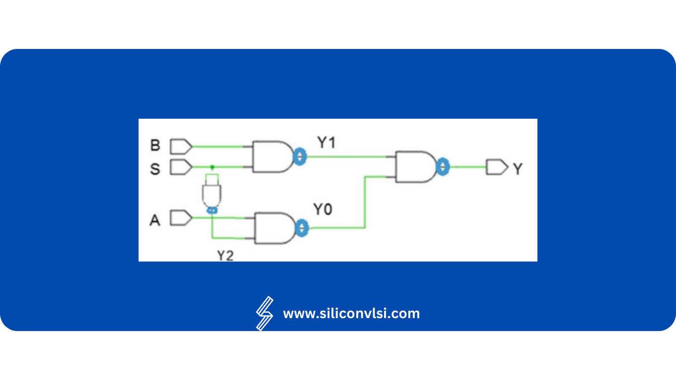
Step-by-Step 2-to-1 MUX Configuration with NAND Gate Logic
As we are familiar with the fact that the NAND is the universal gate, we can implement any logic function using a minimum number of NAND gates. Now let us implement 2:1 mux using a minimum number of 2-input NAND gates. What should be our strategy to implement the 2:1 mux? Use the following steps to implement the 2:1 mux using a minimum number of NAND gates. Through several control lines, a multiplexer is used to combine several analog or digital signals into a single o/p signal.
Let us use the 2:1 mux design: To get the realization of 2:1 mux using NAND gates use the bubbles at the output of each AND gate. The bubble indicates complement or NOT, we will be able to get the NAND gate. But this will change the Boolean function so place a bubble at each input of the OR gate. This will give us the same Boolean function as even NOT gates in cascade will give output the same as the input
The next step is to use De Morgan’s theorem. As we know bubbled OR is equal to NAND replace the bubbled OR using 2-input NAND Replace the bubble shown in the box by using the NOT gate which is designed by using 2-input NAND

Application of 2:1 Multiplexer
The 2:1 multiplexer, also known as a 2-to-1 mux, is a digital logic component that is widely used in various applications. It serves the purpose of selecting one of two input signals and routing it to the output based on a select signal. Here are some of the main uses of a 2:1 mux:
Signal Selection: The primary purpose of a 2:1 multiplexer is for us to select between two input signals and route the chosen signal to the output. You use the select signal, usually labeled as S or SEL, to decide which input signal gets transmitted. When the select signal is low (0), we transmit the first input; when it’s high (1), the second input is transmitted.
Data Routing: A 2:1 mux can be used for data routing purposes in digital systems. By selecting between different input sources, the mux allows for dynamic control of data flow. This is particularly useful when there is a need to switch between different data sources based on specific conditions or events.
Logic Function Implementation: The 2:1 mux can be utilized to implement various logic functions. By appropriately connecting the input signals and configuring the select signal, the mux can behave as a basic logic gate such as an AND gate, OR gate, or XOR gate. This is achieved by mapping the truth table of the desired logic function to the inputs and select signal of the mux.
Signal Level Shifting: In certain cases, a 2:1 mux can be used for signal level shifting purposes. By connecting two signals with different voltage levels to the inputs and selecting the appropriate input with the selected signal, the mux allows for the conversion of one signal level to another.
Address Selection: In memory applications, a 2:1 mux can be used for address selection. By connecting the address lines of a memory device to the inputs of the mux and using the select signal to choose between two address sources, the mux determines the memory location to access.
Multiplexing/Demultiplexing: A 2:1 mux can be employed for multiplexing (combining) or demultiplexing (separating) signals. When used as a multiplexer, it can combine multiple signals into a single output based on the selected signal. When used as a demultiplexer, it can distribute a single input signal to one of two outputs based on the selected signal.
Arithmetic Operations: A 2:1 mux can be utilized for basic arithmetic operations. By connecting the inputs with the binary representations of numbers and configuring the select signal, the mux can select between different inputs to perform addition, subtraction, or other arithmetic operations.