
8-bit Magnitude Comparator: Comparing Binary Numbers
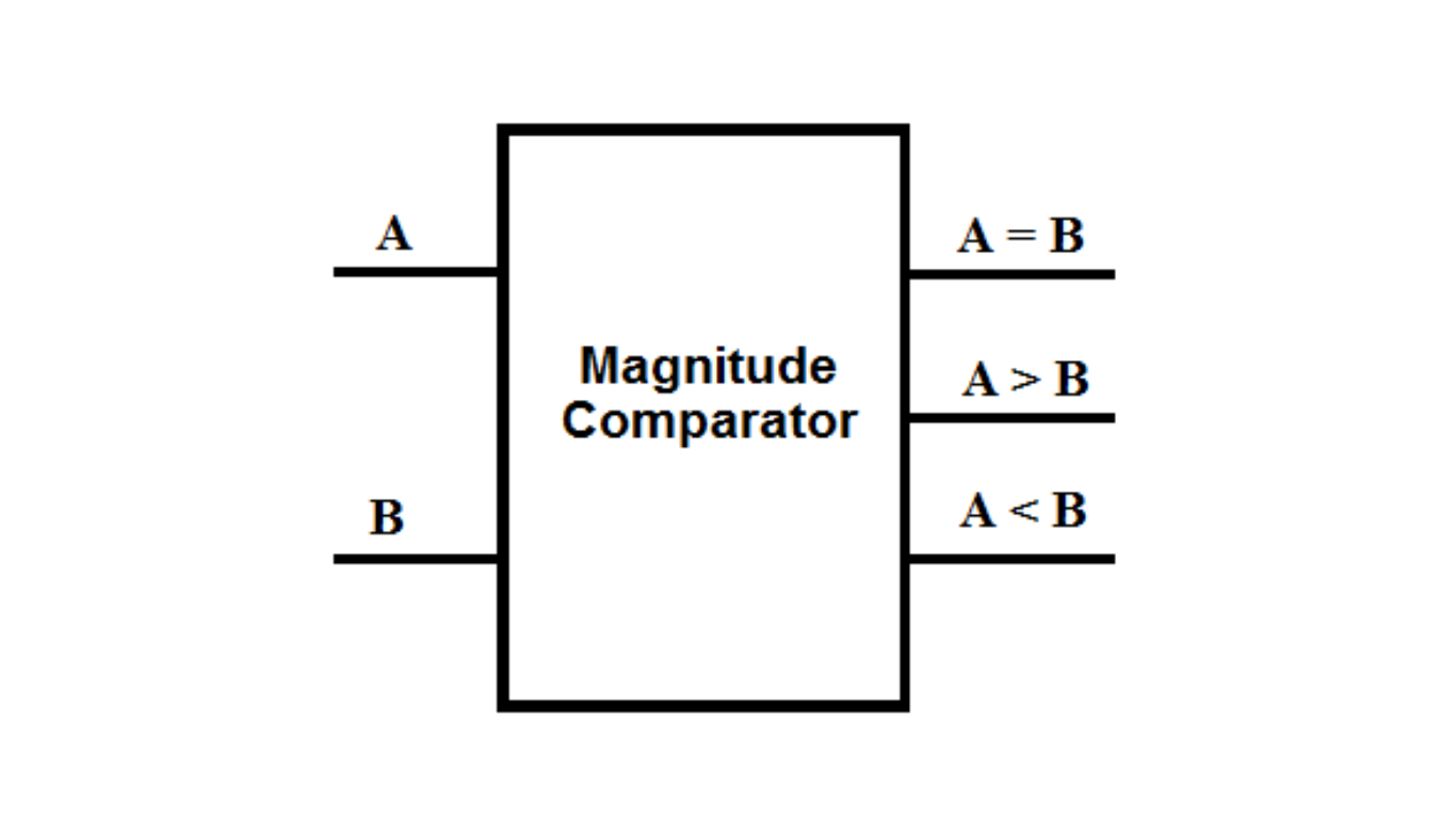
An 8-bit magnitude comparator is a circuit that compares two 8-bit binary values and produces a 1-bit flag as a result, indicating whether the first value is greater than, less than, or equal to the second value. The block diagram of the comparator is shown in Figure 1. In Verilog, the reg data type is treated as an unsigned integer number of the specified width. Therefore, a comparison like 0 and -5 results in (0 < -5). This is because the 2’s complement representation of -5 is 251, and indeed 0 is less than 251.
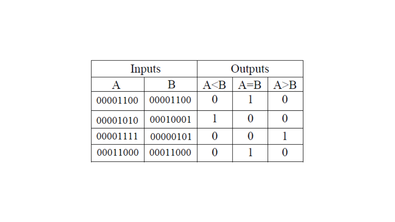
Truth Table for 8-bit Magnitude Comparator
The truth table for the 8-bit magnitude comparator is shown in Figure 2. The comparator takes two 8-bit input signals, A and B, and compares their magnitudes. The three 1-bit output signals are A < B, A = B, and A > B.
General Truth Tabel:
The truth table for a 4-bit magnitude comparator:
| A (4-bit) | B (4-bit) | A > B | A < B | A = B |
|---|---|---|---|---|
| 0000 | 0000 | 0 | 0 | 1 |
| 0000 | 0001 | 0 | 1 | 0 |
| 0000 | 0010 | 0 | 1 | 0 |
| 0000 | 0011 | 0 | 1 | 0 |
| 0000 | 0100 | 0 | 1 | 0 |
| 0000 | 0101 | 0 | 1 | 0 |
| … | … | … | … | … |
| 1111 | 1110 | 1 | 0 | 0 |
| 1111 | 1111 | 0 | 0 | 1 |
In the truth table, A and B represent two 4-bit binary numbers being compared. The output A > B is 1 (True) if A is greater than B, otherwise 0 (False). Similarly, A < B is 1 (True) if A is less than B, otherwise 0 (False). Finally, A = B is 1 (True) if A is equal to B, otherwise 0 (False). The table shows all possible combinations of inputs and their corresponding comparison results for a 4-bit magnitude comparator.
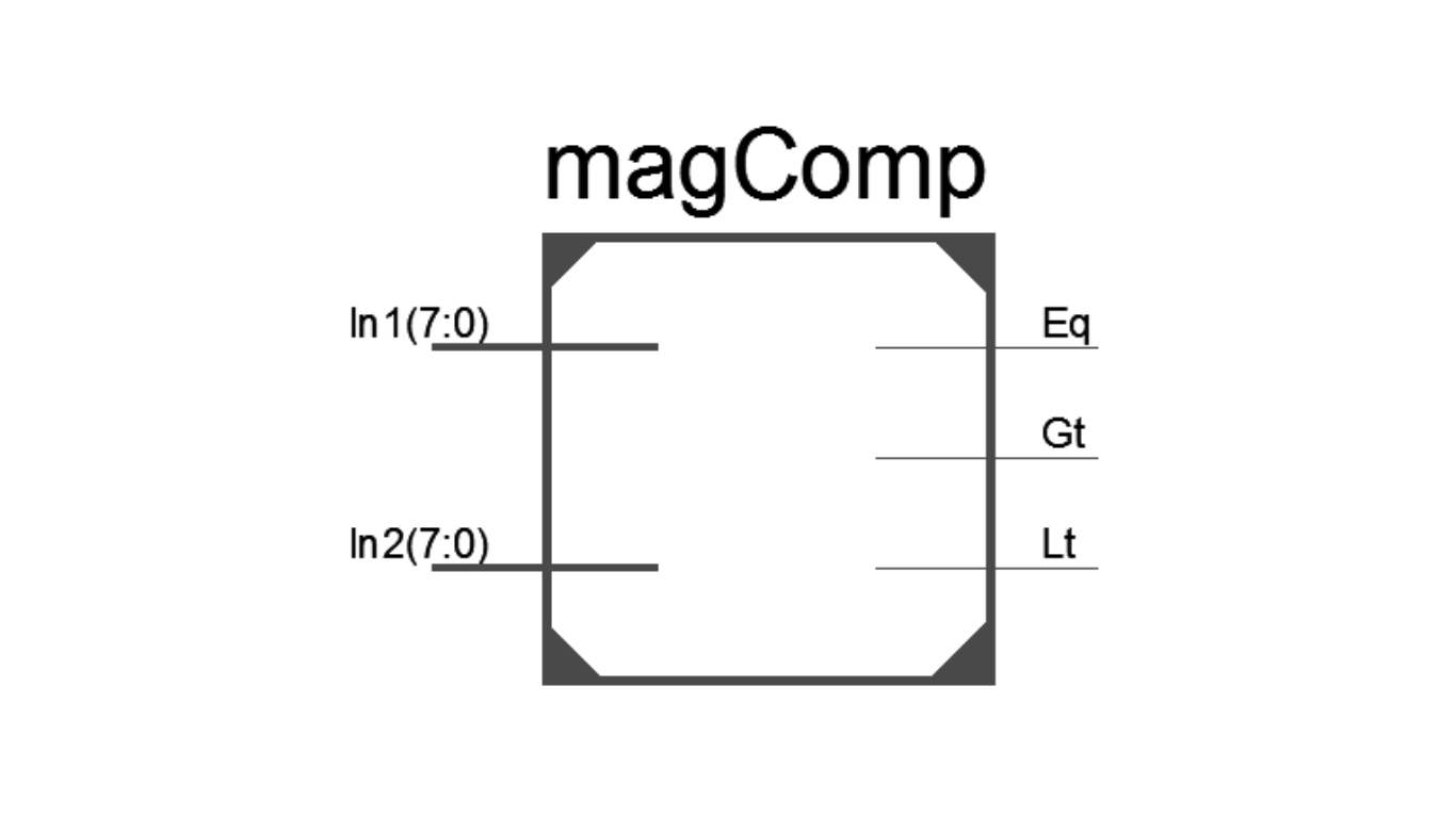
Verilog Module: 8-bit Magnitude Comparator
Figure 3 displays the Verilog module for the 8-bit magnitude comparator. The module has two 8-bit input ports, In1 and In2, and three 1-bit output ports, Gt, Lt, and Eq.
Verilog Code for 8-bit Magnitude Comparator
module magComp (
input [7:0] In1,
input [7:0] In2,
output Gt,
output Lt,
output Eq
);
reg Gt, Lt, Eq;
always @ (In1 or In2) // Check the state of the input lines
begin
Gt <= (In1 > In2) ? 1’b1 : 1’b0;
Lt <= (In1 < In2) ? 1’b1 : 1’b0;
Eq <= (In1 == In2) ? 1’b1 : 1’b0;
end
endmodule
Verilog Test Bench: 8-bit Magnitude Comparator
The Verilog test bench for the 8-bit magnitude comparator is demonstrated in Figure 5. It tests the functionality of the comparator by providing stimulus to the input ports (In1 and In2) and observing the output ports (Gt, Lt, and Eq)
module magComp_tb;
// Inputs
reg [7:0] In1;
reg [7:0] In2;
// Outputs
wire Gt;
wire Lt;
wire Eq;
// Instantiate the Unit Under Test (UUT)
magComp uut (
.In1(In1),
.In2(In2),
.Gt(Gt),
.Lt(Lt),
.Eq(Eq)
);
initial begin
// Initialize Inputs
In1 = 8’b0;
In2 = 8’b0;
// Wait 100 ns for global reset to finish
#100;
// Add stimulus here
In1 = 8’d8;
In2 = 8’d7;
#20;
In1 = 8’d100;
In2 = 8’d120;
#20;
In1 = 8’d250;
In2 = 8’d250;
#20;
In1 = 8’d0;
In2 = -8’d5;
#20;
In1 = -8’d5;
In2 = -8’d5;
#20;
end
endmodule
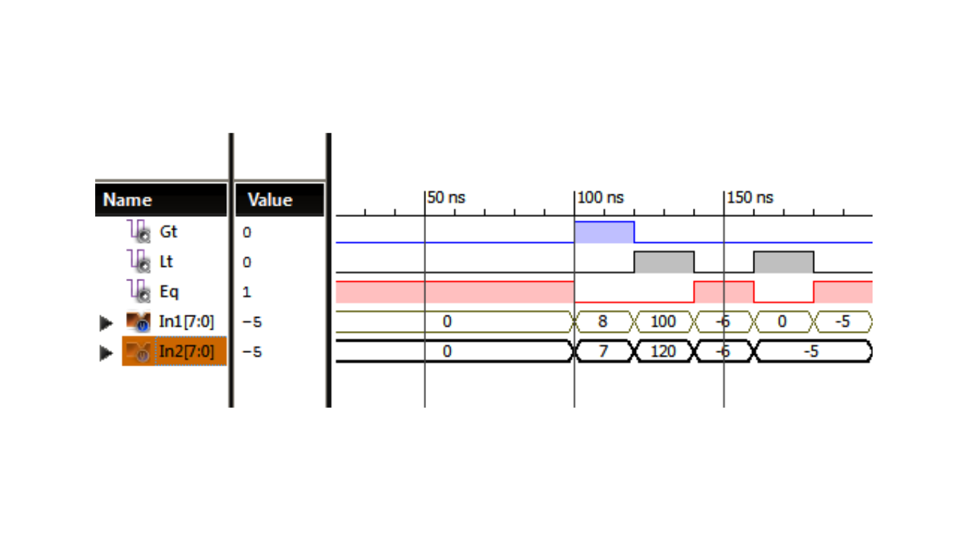
Timing Diagram for 8-bit Magnitude Comparator
Following figure presents the timing diagram of the 8-bit magnitude comparator, illustrating the waveforms of the output signals Gt, Lt, and Eq as the input numbers are compared.
The 8-bit magnitude comparator is an important component in digital systems, used to make decisions based on the relative magnitudes of binary numbers. The provided Verilog module and test bench ensure accurate and reliable comparison of 8-bit values.