
BJTs vs. MOSFETs
When designing analog circuits, understanding the fundamental differences between BJTs (Bipolar Junction Transistors) and MOSFETs (Metal-Oxide-Semiconductor Field-Effect Transistors) is important. While BJTs have been around for decades and are well-modeled, MOSFETs have evolved with modern analog design, often borrowing concepts from BJT modeling. However, this crossover can sometimes lead to incorrect assumptions. Let’s dive into the key differences that matter in analog circuit design.
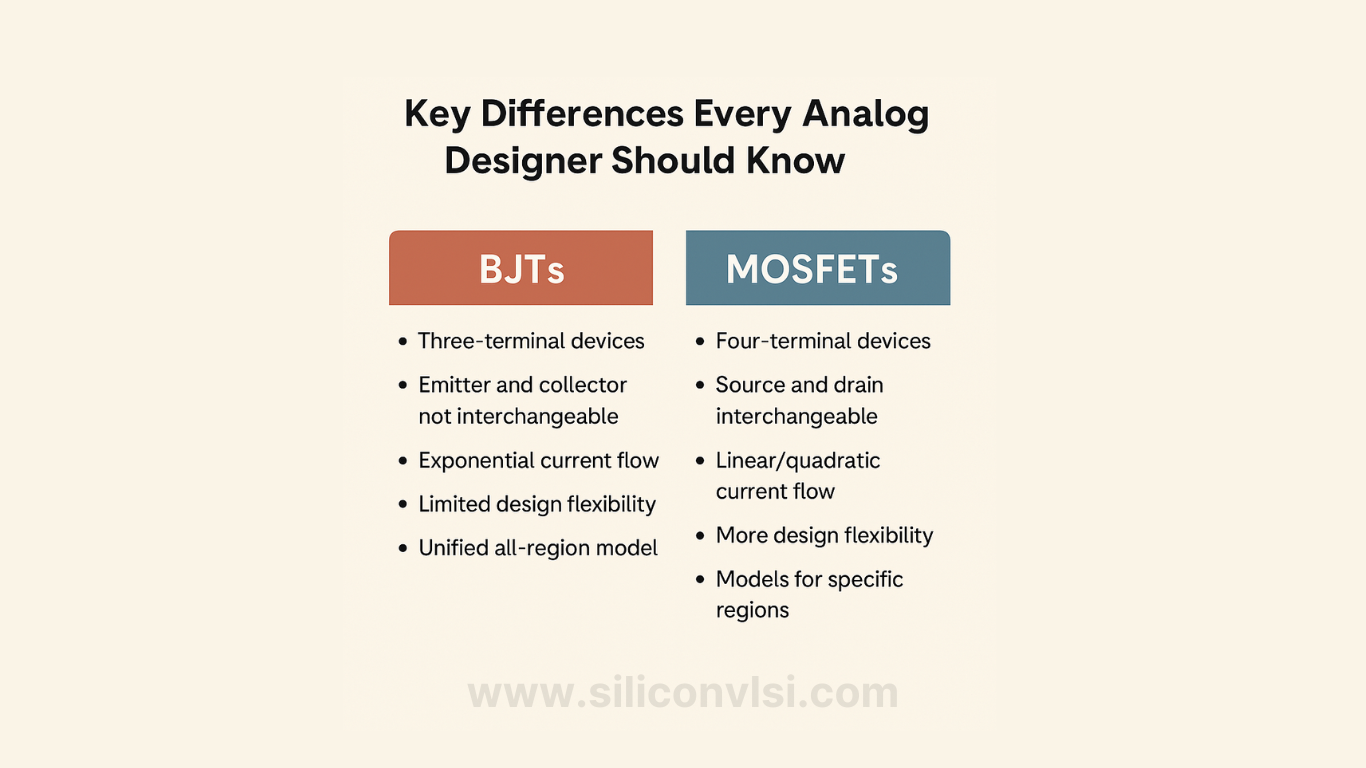
BJTs Are Three-Terminal, While MOSFETs Are Four-Terminal Devices
One of the biggest differences is in the number of terminals:
-
BJTs have three terminals: Base, Collector, and Emitter.
-
MOSFETs have four terminals: Gate, Source, Drain, and Bulk.
Since MOSFETs have an additional bulk (body) terminal, we need three independent voltages (VGB, VSB, and VDB) to define the state of the device, unlike BJTs, which only require two (VBE and VCE). This makes MOSFET modeling more complex, requiring more parameters to capture its behavior accurately.
Source and Drain Are Interchangeable in MOSFETs, Unlike BJTs
In a BJT, the emitter and collector are not interchangeable, meaning current always flows in one direction when the transistor is active. However, in a MOSFET, the source and drain can be swapped, depending on the biasing conditions.
For analog MOS design, it’s often better to use VGB (Gate-to-Bulk) and VSB (Source-to-Bulk) as control voltages rather than VGS (Gate-to-Source) and VBS (Body-to-Source) to properly model the body effect and preserve the symmetry of the MOSFET.
Current Flow: Exponential in BJTs, Linear/Quadratic in MOSFETs
BJTs follow an exponential current law, where the collector current depends exponentially on the base-emitter voltage (IC ∝ e^(VBE/VT)).
In MOSFETs, current behavior varies by region:
-
Weak inversion (subthreshold region) → Exponential current flow (like a BJT)
-
Strong inversion (saturation/linear region) → Quadratic or linear dependence on gate voltage
-
Moderate inversion → A transition region where neither model fully applies
This difference comes from the underlying physics: BJTs rely on diffusion current, while MOSFETs operate through drift current in strong inversion.
More Design Flexibility with MOSFETs
With BJTs, the emitter area is the only real geometric design parameter, limiting flexibility. MOSFETs, on the other hand, allow designers to tweak both width (W) and length (L) to optimize performance. This gives MOSFETs more flexibility in analog design, where controlling parameters like gain, bandwidth, and power consumption is essential.
MOSFET Models Are Less Unified Than BJTs
BJTs benefit from a well-established, all-region model like the Ebers-Moll model, which provides a simple yet effective framework for hand calculations and simulations.
MOSFET models, however, are often developed for specific regions of operation. As a result, important parameters like gate transconductance (gm) and gate-to-source capacitance (Cgs) can be discontinuous across regions, creating mismatches between hand calculations and circuit simulations.
Final Thoughts
If you’re designing high-performance analog circuits, understanding these key differences between BJTs and MOSFETs will help you make better design decisions. While BJTs offer stable, well-defined models, MOSFETs provide greater flexibility but require careful modeling to avoid discontinuities.
Would you rather work with BJTs for their predictability or MOSFETs for their design flexibility? Let’s discuss in the comments below!
2 Comments
Really informative material here!
Nice article