

Clock Skew and Uncertainty
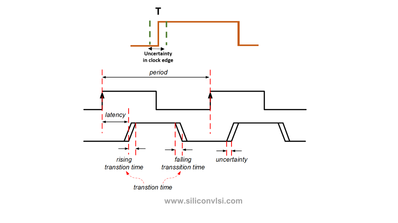
Clock Skew vs Clock Uncertainty: 7 Key Differences Explained
Clock skew and clock uncertainty are both important concepts in VLSI timing analysis. Although they are related to clock timing, they describe different types of timing variation and affect setup and hold analysis in different ways.
Understanding the difference between clock skew and clock uncertainty is essential for physical design, static timing analysis (STA), and timing closure.
What Is Clock Skew?
Clock skew is the difference in clock arrival time between two sequential elements, such as a launch flip-flop and a capture flip-flop.
Ideally, the clock should reach all flip-flops at the same time. In a real IC, however, differences in clock-tree path length, buffer delays, routing, and parasitic effects cause the clock to arrive at different times.
For example:
- Clock reaches the launch flip-flop at 1.00 ns
- Clock reaches the capture flip-flop at 1.08 ns
The clock skew is:
Clock Skew = Capture Clock Arrival − Launch Clock Arrival
= 1.08 − 1.00 = +0.08 ns
Therefore, the skew is +80 ps.
Clock skew can affect both setup and hold timing.
Types of Clock Skew
Clock skew is commonly described as positive skew or negative skew.
Positive Clock Skew
Positive skew occurs when the capture clock arrives later than the launch clock.
For example:
Launch clock = 1.00 ns
Capture clock = 1.10 ns
Therefore:
Skew = +0.10 ns
Positive skew generally provides additional time for setup timing, but it can make hold timing more difficult.
Negative Clock Skew
Negative skew occurs when the capture clock arrives earlier than the launch clock.
For example:
Launch clock = 1.00 ns
Capture clock = 0.92 ns
Therefore:
Skew = −0.08 ns
Negative skew generally makes setup timing more difficult but can provide additional hold margin.
In practical clock-tree analysis, skew is determined from the actual clock arrival times at the relevant sequential endpoints.
What Is Clock Uncertainty?
Clock uncertainty represents the timing margin used to account for variations and unpredictability in clock arrival or clock edge position.
It can account for effects such as:
- Clock jitter
- PLL/DLL variations
- Phase noise
- Clock-source variation
- Modeling uncertainty
- Other timing variations considered by the timing methodology
Clock uncertainty is normally represented as a timing margin in static timing analysis.
For example, if the clock period is 1 ns and the analysis includes 50 ps of uncertainty, the timing analysis does not assume that the clock edge is perfectly predictable.
This reduces the available timing margin and makes the design more robust against clock variations.
Clock Jitter vs Clock Uncertainty
Clock jitter and clock uncertainty are related, but they are not exactly the same thing.
Clock Jitter
Clock jitter describes the variation of a clock edge around its ideal position in time.
For example, an ideal clock edge might occur at:
10.000 ns
But actual edges could occur around:
9.970 ns, 10.015 ns, 9.985 ns, 10.025 ns
This variation is clock jitter.
Clock Uncertainty
Clock uncertainty is the timing margin used during STA to account for clock-related variations.
Therefore:
Jitter can be one contributor to clock uncertainty.
It is better to avoid treating the terms as exact synonyms.
Clock Skew vs Clock Uncertainty
The fundamental difference is that skew describes a difference between clock arrival times, while uncertainty represents a margin for timing variation or lack of certainty in the clock timing.
| Parameter | Clock Skew | Clock Uncertainty |
|---|---|---|
| Meaning | Difference between clock arrival times | Timing margin for clock variation |
| Main concept | Relative clock timing | Timing variation/margin |
| Typical source | Clock-tree path and buffer differences | Jitter and other clock variations |
| Deterministic component | Often analyzed as a measurable quantity | May represent modeled variation |
| STA impact | Changes launch/capture relationship | Reduces available timing margin |
| Setup impact | Can improve or worsen setup | Generally makes timing more conservative |
| Hold impact | Can improve or worsen hold | Can reduce timing margin |
| Analysis | Clock arrival-time analysis | Timing-margin analysis |
| Physical design relevance | CTS and clock-tree optimization | Timing signoff and variation modeling |
1. Difference in Nature
Clock Skew
Clock skew is fundamentally a relative timing difference.
It asks:
When does the clock arrive at one endpoint compared with another endpoint?
Clock Uncertainty
Clock uncertainty asks:
How much timing margin should be reserved because the clock edge is not perfectly predictable?
This is the most important conceptual distinction.
2. Difference in Causes
Clock skew can result from:
- Different clock-tree path lengths
- Buffer delay differences
- Routing differences
- Clock-tree topology
- Load differences
- On-chip variation and parasitic effects
Clock uncertainty can include:
- Clock jitter
- PLL variation
- Phase noise
- Clock-source uncertainty
- Modeling margins
- Other methodology-dependent variation
3. Effect on Setup Timing
Consider a simple setup path:
Launch Flip-Flop → Combinational Logic → Capture Flip-Flop
The available time depends on the relationship between the launch and capture clock edges.
If the capture clock arrives later, positive skew can provide additional setup time.
Clock uncertainty, on the other hand, is generally included as a penalty or margin, reducing the timing budget available for the data path.
A simplified setup relationship can be represented as:
Required Time ≈ Clock Period + Capture Skew − Setup Time − Uncertainty
The exact STA equation depends on the timing model and whether the analysis is for setup or hold.
4. Effect on Hold Timing
Hold timing is concerned with ensuring that newly launched data does not reach the capture flip-flop too early.
Positive skew can make hold timing more difficult because the capture clock arrives later relative to the launch clock.
Uncertainty can also reduce hold margin depending on how it is modeled and whether the analysis is using early/late clock variation.
Therefore, skew and uncertainty should be considered separately when debugging a hold violation.
5. Clock Skew Is Not the Same as Clock Jitter
This is an important interview question.
Clock skew:
Difference in clock arrival time between two locations.
Clock jitter:
Variation of a clock edge from its ideal or expected timing position.
For example, suppose:
- Clock reaches FF1 at 2.00 ns
- Clock reaches FF2 at 2.08 ns
The difference is 80 ps of skew.
If the clock edge itself moves between 1.97 ns and 2.03 ns over different cycles, that variation is jitter.
6. Why Clock Tree Synthesis Is Important
Clock Tree Synthesis (CTS) attempts to distribute the clock signal to sequential elements while controlling important parameters such as:
- Clock skew
- Clock latency
- Transition time
- Clock-tree power
- Routing congestion
The objective is not simply to make every clock path physically identical. Instead, CTS aims to create a clock network that satisfies the design’s timing and electrical requirements.
After CTS, timing analysis is performed to identify:
- Setup violations
- Hold violations
- Excessive skew
- Clock transition violations
- Other clock-related problems
7. Why Clock Uncertainty Is Important in STA
No practical clock is perfectly ideal.
Even when the clock tree is carefully designed, variations can occur because of:
- Manufacturing variation
- Voltage variation
- Temperature variation
- PLL behavior
- Supply noise
- Crosstalk
- Phase noise
- Clock-source characteristics
Clock uncertainty provides timing margin so that the design does not operate correctly only under an unrealistically perfect clock condition.
Clock Skew and Uncertainty Example
Consider two flip-flops:
Launch FF clock arrival = 0.80 ns
Capture FF clock arrival = 0.90 ns
Therefore:
Clock Skew = 0.90 − 0.80 = +0.10 ns
So the capture clock arrives 100 ps later.
Now assume the STA methodology uses:
Clock uncertainty = 50 ps
The design must satisfy timing with this additional margin taken into account.
The important point is:
100 ps skew ≠ 50 ps uncertainty
They represent different timing concepts.
Clock Skew vs Clock Uncertainty: Simple Example
Imagine two runners starting a race.
The clock skew is similar to the difference between when the two runners actually receive the starting signal.
The clock uncertainty is similar to allowing some extra margin because the exact timing of the starting signal is not perfectly predictable.
So:
Skew → difference between clock arrivals
Uncertainty → margin for clock timing variation
This is a useful way to remember the distinction.
How They Appear in Physical Design
During the physical-design flow, clock timing becomes increasingly realistic.
A simplified flow is:
Synthesis → Floorplanning → Placement → CTS → Routing → Parasitic Extraction → STA
Before CTS, clocks are often modeled using idealized assumptions.
After CTS, actual clock-tree paths can be analyzed, allowing designers to calculate clock arrival times and skew.
After routing and extraction, additional parasitic and variation effects can be incorporated into timing signoff.
Common Mistakes
Mistake 1: Saying skew and uncertainty are the same
They are not.
Skew is a relative difference in clock arrival times, while uncertainty is a timing margin representing clock variation or modeling uncertainty.
Mistake 2: Calling all uncertainty “random”
In practical STA, uncertainty is a methodology/modeling quantity and can include multiple components. It should not automatically be described as purely random.
Mistake 3: Saying positive skew always improves timing
Positive skew can help setup but hurt hold.
The effect depends on which timing check is being analyzed.
Mistake 4: Treating jitter and uncertainty as identical
Jitter can contribute to uncertainty, but the terms are not universally interchangeable.
Frequently Asked Questions
What is the main difference between clock skew and clock uncertainty?
Clock skew is the difference in clock arrival times between two endpoints, whereas clock uncertainty represents a timing margin used to account for clock variations and related uncertainty.
Is clock skew good or bad?
It depends on the timing check. Positive skew can help setup timing but may hurt hold timing, while negative skew can have the opposite tendency.
Is clock jitter the same as clock uncertainty?
No. Jitter is a variation in the timing of clock edges. Clock uncertainty is a margin used in timing analysis to account for jitter and/or other clock-related variations.
Why is clock uncertainty used in STA?
It prevents timing analysis from assuming an unrealistically perfect clock and provides margin for clock-related variations.
Which tool handles clock skew?
Clock skew is analyzed as part of static timing analysis and clock-tree analysis. CTS tools are also used to build and optimize the clock network.
Does clock uncertainty affect setup and hold?
Yes. The exact effect depends on the STA methodology, timing corner, and how the uncertainty is specified for setup and hold checks.
Key Takeaways
- Clock skew is the difference between clock arrival times at different endpoints.
- Positive skew means the capture clock arrives later than the launch clock.
- Negative skew means the capture clock arrives earlier.
- Clock uncertainty represents timing margin for clock variation and modeling effects.
- Clock jitter can be one contributor to clock uncertainty.
- Skew and uncertainty both affect timing closure but represent different concepts.
- CTS primarily focuses on building and optimizing the clock distribution network.
- STA uses clock arrival information and uncertainty to determine setup and hold timing.
- A good physical-design engineer should analyze skew, jitter, uncertainty, latency, and timing violations separately.