AND Gate Truth Table with Symbol and Diagram
When you use an AND gate, you’re working with a logic gate that has two or more inputs and a single output. It follows the basic principle of Boolean logic: the output is true (high) only when all the inputs are true (high). In simpler terms, the AND gate’s output is 1 only if all its inputs are 1; otherwise, the output will be 0. You can think of this behavior as similar to the logical “AND” operation we use in everyday language.

To understand the working of an AND gate, let’s consider a simple example with two inputs, A and B. The AND gate compares the states of these inputs and produces an output based on their logical conjunction. If both inputs A and B are true (high), the output will be true (high). However, if either or both of the inputs are false (low), the output will be false (low).
In terms of voltage levels, an AND gate operates based on the principle of a positive logic system. When the inputs receive a voltage representing true (high) or false (low), the AND gate processes this information and deliver the corresponding output voltage.
Truth Table and Logic Symbol
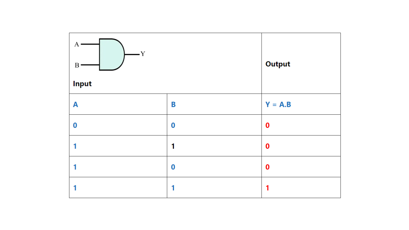
The behavior of an AND gate can be represented using a truth table. Table 1 shows the truth table for a 2-input AND gate:
| Input A | Input B | Output |
|---|---|---|
| 0 | 0 | 0 |
| 0 | 1 | 0 |
| 1 | 0 | 0 |
| 1 | 1 | 1 |
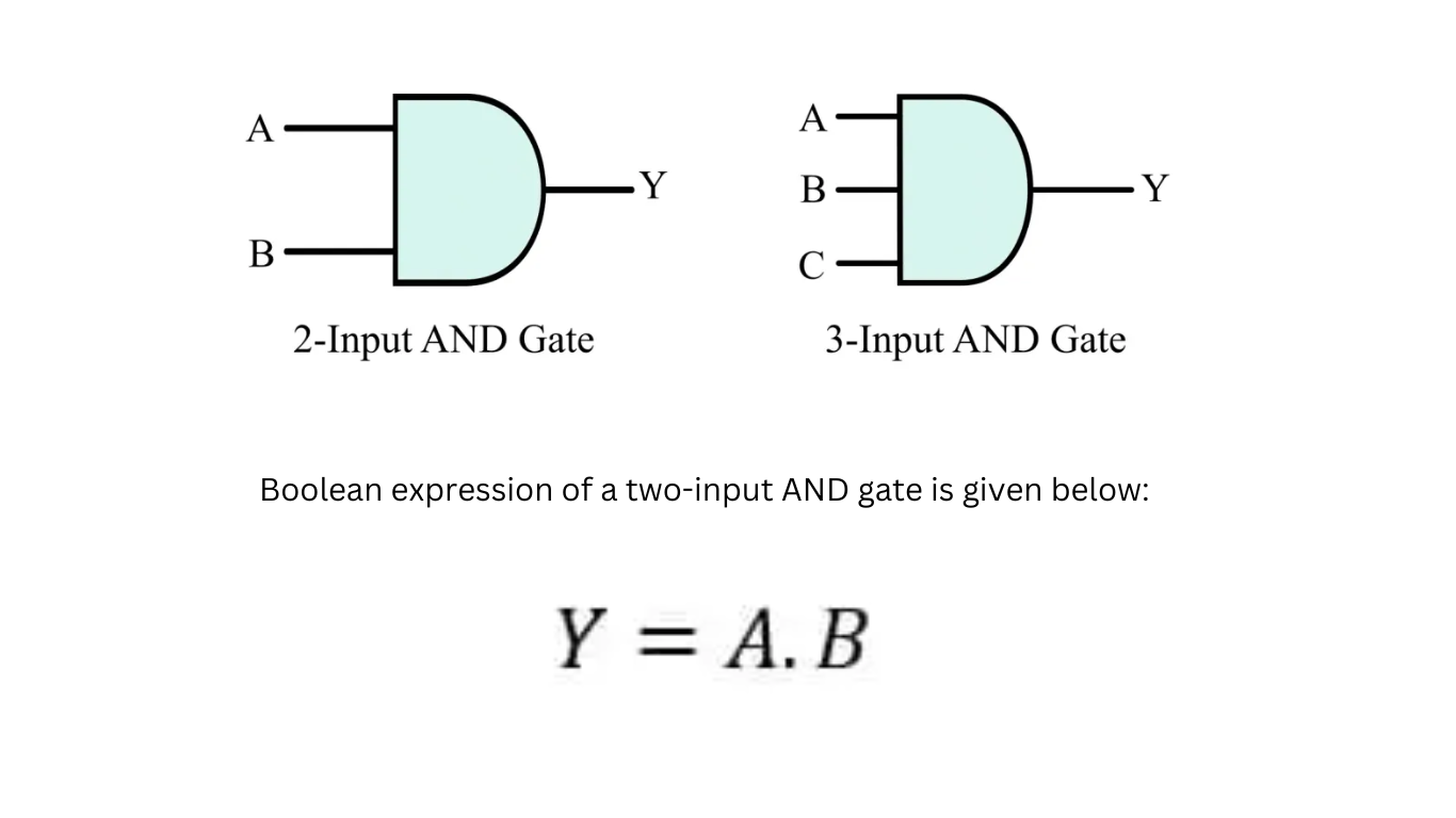
The logic symbol for an AND gate is a triangle with inputs on the left side and a single output on the right side. The inputs are labeled as A and B, and the output is denoted as Y. This graphical representation helps in visualizing the connections between different logic gates in a circuit.
Applications of AND Gates
AND gates find widespread applications in various fields, ranging from digital electronics to computer science. Here are some common applications of AND gates:
Boolean Logic Operations: AND gates are fundamental components used in performing logical operations, such as conjunction, in Boolean algebra and digital logic circuits.
Data Validation: In computer systems AND gates are employed to verify and validate data before processing. They ensure that specific conditions are met before allowing further operations.
Multiplexers and Demultiplexers: AND gates are used in multiplexers and demultiplexers to enable the selection of input/output lines based on specific control signals.
Memory Units: In memory systems, AND gates help control the read and write operations by enabling or disabling specific lines based on the address and control signals.
Address Decoders: AND gates are used in address decoders to decode binary addresses and select specific memory locations.
Advantages of Using AND Gates
Using AND gates offers several advantages in the field of digital logic design and electronic systems:
Simplicity: AND gates are simple and easy to understand, making them ideal for building complex circuits.
Reliability: Due to their basic structure and operation, AND gates are reliable and less prone to errors.
Low Power Consumption: AND gates consume minimal power, making them energy-efficient components in electronic systems.
Fast Response Time: AND gates exhibit fast response times, allowing for quick and efficient processing of logic operations.
Limitations of AND Gates
While AND gates are essential in digital logic, they also have certain limitations that should be considered:
Output Dependency: The output of an AND gate solely depends on the input states. If any input fails or changes, it affects the output, leading to potential issues in complex circuits.
Lack of Flexibility: AND gates have limited flexibility as they can only perform the logical conjunction operation. To achieve more complex functions, additional logic gates and circuitry are required.
Propagation Delay: Each logic gate introduces a certain delay in signal propagation. When multiple AND gates are cascaded, the overall delay can impact the performance of the system.
Types of AND Gates
There are different variations of AND gates designed to suit specific requirements. Some common types of AND gates include:
2-input AND Gate: The basic AND gate with two inputs and one output, as discussed earlier.
3-input AND Gate: An AND gate with three inputs and one output, extending the concept of logical conjunction to three variables.
4-input AND Gate: A higher-level AND gate with four inputs and one output, allowing for more complex logical operations.
AND Gate in Digital Logic Design: In digital logic design, AND gates are essential building blocks used to construct circuits for various applications. They serve as key components in the implementation of logical functions, such as multiplexers, adders, memory units, and arithmetic logic units (ALUs). By combining multiple AND gates, complex circuits and systems can be designed to perform intricate operations.
Implementing AND Gates in Integrated Circuits AND gates are not only conceptual entities but are also realized as physical components in integrated circuits (ICs). These ICs contain transistors and other electronic components to create functional AND gates on a silicon chip. By integrating multiple AND gates into a single IC, manufacturers can produce highly compact and efficient digital logic devices.
Troubleshooting and Common Issues In complex digital circuits involving AND gates, troubleshooting becomes important in identifying and rectifying issues. Common problems encountered with AND gates include incorrect input connections, faulty ICs, or timing-related errors. By carefully examining the circuit and verifying the inputs and outputs, one can diagnose and resolve these issues effectively.
Future Developments and Trends As technology continues to advance, the field of digital logic and electronic systems is witnessing constant evolution. The future developments in AND gates are expected to focus on improving speed, reducing power consumption, and enhancing integration capabilities. Researchers and engineers are exploring novel materials, designs, and architectures to push the boundaries of digital logic.
How Does an AND Gate Work?
The operation of a two-input AND gate for different input combinations is explained in the following bullet points:
- When A = 0 and B = 0, the output Y = 0.
- When A = 0 and B = 1, the output Y = 0.
- When A = 1 and B = 0, the output Y = 0.
- When A = 1 and B = 1, the output Y = 1.
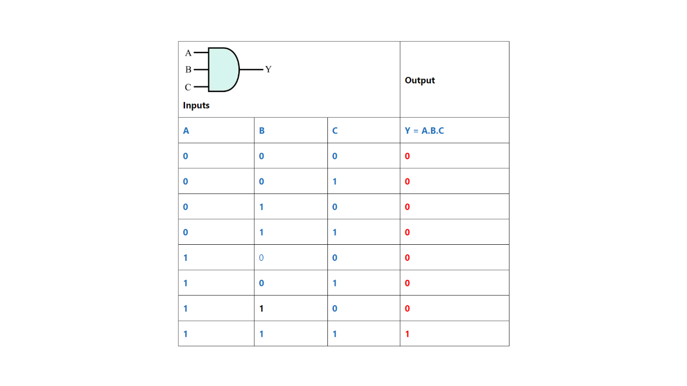
The operation of a three-input AND gate for different possible input combinations is described below:
- When A = 0, B = 0, and C = 0, the output Y = 0.
- When A = 0, B = 0, and C = 1, the output Y = 0.
- When A = 0, B = 1, and C = 0, the output Y = 0.
- When A = 0, B = 1, and C = 1, the output Y = 0.
- When A = 1, B = 0, and C = 0, the output Y = 0.
- When A = 1, B = 0, and C = 1, the output Y = 0.
- When A = 1, B = 1, and C = 0, the output Y = 0.
- When A = 1, B = 1, and C = 1, the output Y = 1.
Truth Table of AND Gate
2 Input AND Gate
The truth table of a two input AND gate is given below:

3 Input AND Gate

n summary, the AND gate is a fundamental component of digital logic and plays a important role in various electronic systems. Its ability to perform logical conjunction based on input states makes it an indispensable tool in designing complex circuits. By understanding the working principles, applications, advantages, and limitations of AND gates, engineers and enthusiasts can leverage this knowledge to create innovative solutions in the field of digital electronics.
FAQs
Q1. Can an AND gate have more than two inputs?
Yes, AND gates can have multiple inputs. There are 3-input, 4-input, and even higher-input AND gates available, allowing for the conjunction of multiple variables.
Q2. Can I use an AND gate as a basic building block for all logic operations?
While AND gates are essential components, they alone cannot perform all logic operations. Other logic gates like OR, NOT, and XOR gates are also necessary to implement a wide range of functions.
Q3. What happens if I connect the output of an AND gate to one of its inputs?
Connecting the output of an AND gate to one of its inputs creates a feedback loop, resulting in an unstable state known as a race condition. This can lead to unpredictable and unreliable behavior in the circuit.
Q4. Are there any alternatives to AND gates in digital logic?
Yes, there are alternative gates such as NAND gates, NOR gates, and XOR gates that can be used to perform the logical conjunction operation, often with additional functionality.
Q5. How are AND gates manufactured in integrated circuits?
AND gates, along with other logic gates, are manufactured using semiconductor fabrication techniques. Transistors and other components are patterned on a silicon substrate, creating the necessary circuitry for AND gate functionality.
OR Gate- Symbol, Truth Table, and Circuit Diagram
AND Gate- Symbol, Truth Table, and Circuit Diagram
NOR Gate- Symbol, Truth Table, and Circuit Diagram
NAND Gate- Symbol, Truth Table, and Circuit Diagram