

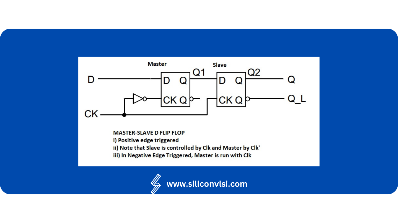
Master-Slave D Flip-Flop Positive or Negative Edge-Triggered
Master-Slave D Flip-Flop: Positive vs Negative Edge-Triggered
A Master-Slave D Flip-Flop is a sequential circuit used to store and transfer one bit of digital data in synchronization with a clock signal. It is built from two clock-controlled storage stages called the master and slave.
The clocking arrangement determines whether the circuit behaves as a positive-edge-triggered or negative-edge-triggered flip-flop.
Understanding this distinction is important in digital VLSI, synchronous design, registers, counters, and sequential circuits.

What Is a Master-Slave D Flip-Flop?
A master-slave D flip-flop consists conceptually of two level-sensitive storage elements connected in cascade:
- Master stage
- Slave stage
The two stages are controlled by complementary phases of the clock.
The purpose of this arrangement is to prevent the output from following the input throughout an entire clock level.
Instead, the input is sampled during one clock phase and the stored value becomes available at the output during the opposite phase.
This creates edge-triggered behavior.
How Does a Master-Slave D Flip-Flop Work?
Consider a master-slave arrangement made from two D latches.
The key idea is:
When the master is transparent, the slave is closed.
Then:
When the master is closed, the slave becomes transparent.
Because the two stages operate during opposite clock phases, data does not pass directly from D to Q during the same phase.
The exact clock polarity determines whether the resulting flip-flop responds to the rising edge or falling edge.
Positive-Edge-Triggered Master-Slave D Flip-Flop
A positive-edge-triggered D flip-flop updates its output on the rising edge of the clock.
The rising edge is the transition:
0 → 1
A typical master-slave implementation uses:
- Master latch: transparent when CLK = 0
- Slave latch: transparent when CLK = 1
When CLK = 0
The master is transparent and can capture the D input.
The slave is closed, so Q does not change.
When CLK changes from 0 → 1
The master closes and holds the sampled value.
The slave becomes transparent and transfers the master’s stored value to Q.
Therefore:
Rising edge → D is captured → Q updates
So:
Q(next) = D
at the active rising edge.
Positive-Edge-Triggered Timing
Suppose the input changes several times while the clock is LOW.
The master can follow those changes while it is transparent, but the output remains isolated by the closed slave.
When the clock transitions:
LOW → HIGH
the master stops tracking D.
The value present at the sampling boundary is transferred to the output.
Therefore, the flip-flop effectively samples D at the rising edge.
Negative-Edge-Triggered Master-Slave D Flip-Flop
A negative-edge-triggered D flip-flop updates its output on the falling edge of the clock.
The falling edge is:
1 → 0
A typical master-slave implementation uses the opposite latch arrangement:
- Master latch: transparent when CLK = 1
- Slave latch: transparent when CLK = 0
When CLK = 1
The master is transparent and can track the D input.
The slave is closed, so Q remains unchanged.
When CLK changes from 1 → 0
The master closes and stores the current D value.
The slave becomes transparent and transfers that stored value to Q.
Therefore:
Falling edge → D is captured → Q updates
So:
Q(next) = D
at the active falling edge.
Positive vs Negative Edge-Triggered D Flip-Flop
The fundamental difference is the clock edge at which the flip-flop samples the data.
| Feature | Positive Edge | Negative Edge |
|---|---|---|
| Active clock edge | Rising edge | Falling edge |
| Clock transition | 0 → 1 | 1 → 0 |
| Data sampling | At rising edge | At falling edge |
| Output update | After rising edge | After falling edge |
| Typical master phase | LOW | HIGH |
| Typical slave phase | HIGH | LOW |
Both types can perform the same basic storage function; the important difference is when the data is captured.
Master-Slave D Flip-Flop Truth Table
For a positive-edge-triggered D flip-flop:
| Clock Event | D | Q(next) |
|---|---|---|
| No active edge | X | Q |
| Rising edge | 0 | 0 |
| Rising edge | 1 | 1 |
For a negative-edge-triggered flip-flop, simply replace the active edge with the falling edge.
| Clock Event | D | Q(next) |
|---|---|---|
| No active edge | X | Q |
| Falling edge | 0 | 0 |
| Falling edge | 1 | 1 |
Here, Q in the “No active edge” row means the previous output is retained.
Why Are Two Stages Used?
The master-slave architecture provides an important timing property.
If a single level-sensitive latch were used, its output could change throughout the active clock phase as D changes.
With two complementary stages:
D → Master → Slave → Q
only one stage is transparent at a time.
This prevents the output from continuously following D during the active clock phase.
The arrangement therefore behaves approximately like an edge-triggered storage element.
Positive Edge vs Negative Edge: Which Is Better?
There is no universal answer that one is better than the other.
The choice depends on the timing architecture of the digital system.
A designer may select the active edge based on:
- Clocking methodology
- Setup and hold requirements
- Data-path timing
- Clock distribution
- Interaction with other sequential elements
- Power consumption
- Library availability
- System-level timing constraints
Both rising-edge and falling-edge flip-flops are widely used.
Propagation Delay Considerations
A real flip-flop does not change Q instantaneously when the active clock edge arrives.
There is a delay between the triggering clock edge and the corresponding output transition.
This is called clock-to-Q delay.
For example:
CLK rising edge → internal state change → Q transition
The actual delay depends on:
- Transistor sizing
- Load capacitance
- Process technology
- Circuit topology
- Supply voltage
- Temperature
Therefore, it is not generally correct to claim that positive-edge-triggered flip-flops always have shorter propagation delay than negative-edge-triggered flip-flops.
Their performance depends on the implementation.
Setup and Hold Time
A master-slave D flip-flop also has important timing requirements.
Setup Time
The D input must remain stable for a certain period before the active clock edge.
This period is called setup time.
For example, for a positive-edge-triggered flip-flop:
D stable → setup interval → rising edge
Hold Time
The D input must remain stable for a certain period after the active clock edge.
This is called hold time.
Therefore, correct operation requires both:
Setup time requirement
and
Hold time requirement
If these requirements are violated, the flip-flop can enter an unpredictable or metastable state.
Master-Slave Flip-Flop and Clock Domain Crossing
The original article associates master-slave flip-flops directly with clock-domain crossing.
A more precise description is important here.
A normal master-slave D flip-flop is primarily a sequential storage element. It does not by itself make an arbitrary clock-domain crossing safe.
For a single-bit asynchronous clock-domain crossing, designers commonly use a synchronizer, often consisting of multiple flip-flop stages clocked by the destination clock.
Therefore:
Master-slave structure ≠ complete CDC solution
The flip-flop can be a building block in synchronization circuits, but additional architecture is normally required.
Applications of Master-Slave D Flip-Flops
Master-slave D flip-flops are useful building blocks in many sequential circuits.
Registers
Multiple D flip-flops can be connected in parallel to store multiple bits.
For example, eight flip-flops can form an 8-bit register.
Counters
Flip-flops can be interconnected to create synchronous and asynchronous counters.
State Machines
Finite-state machines use flip-flops to store the current state.
At each active clock edge, the stored state can be updated according to the next-state logic.
Shift Registers
Connecting the Q output of one flip-flop to the D input of another allows data to shift from one stage to the next.
Pipeline Registers
Flip-flops are widely used between combinational logic stages in synchronous digital systems.
They divide long logic paths into smaller timing stages and enable higher operating frequencies.
Positive-Edge and Negative-Edge Flip-Flops in Timing Design
Using both clock edges can sometimes be useful in specialized architectures.
For example, a design may use:
- Rising edge for one group of registers
- Falling edge for another group
This allows data transfer or processing to occur on opposite clock edges.
However, mixed-edge clocking requires careful timing analysis because the available timing interval and clock relationships must be considered.
Master-Slave D Flip-Flop vs D Latch
These two devices should not be confused.
| Feature | D Latch | Master-Slave D Flip-Flop |
|---|---|---|
| Triggering | Level-sensitive | Edge-sensitive |
| Transparency | During active level | Around active edge |
| Storage | One latch | Two complementary stages |
| Output behavior | Can follow D during active level | Changes at clock edge |
| Common use | Timing/control circuits | Registers and synchronous systems |
A master-slave implementation is one way to obtain edge-triggered behavior from level-sensitive storage elements.
Common Misconceptions
1. The Master Captures Data on the Same Edge That the Slave Transfers It
The exact behavior depends on the latch polarity and implementation.
The master and slave operate during complementary clock phases, allowing the circuit to produce edge-triggered behavior.
2. Positive-Edge Means the Master Always Captures Data on the Rising Edge
In a typical master-slave implementation for a positive-edge-triggered flip-flop, the master is transparent during the LOW phase and closes at the rising edge.
The slave then becomes transparent and transfers the stored value to Q.
So it is more accurate to say that the flip-flop samples the data at the rising edge, rather than saying both stages capture data at that edge.
3. Negative-Edge Flip-Flops Are Slower
Not necessarily.
The delay depends on the circuit implementation, transistor sizing, load, process, and other factors.
4. A Master-Slave Flip-Flop Completely Eliminates Metastability
No.
If setup or hold requirements are violated, metastability can still occur.
Frequently Asked Questions
What is a master-slave D flip-flop?
It is a sequential storage circuit made from two complementary clock-controlled storage stages called the master and slave.
Is a master-slave D flip-flop positive or negative edge-triggered?
It can be either. The clock polarity and arrangement of the master and slave stages determine whether the circuit responds to the rising or falling edge.
What is a positive-edge-triggered D flip-flop?
It is a flip-flop that captures D and updates Q on the rising edge (0 → 1) of the clock.
What is a negative-edge-triggered D flip-flop?
It captures D and updates Q on the falling edge (1 → 0) of the clock.
Which edge-triggered flip-flop is better?
Neither is universally better. The appropriate choice depends on the clocking scheme and timing requirements of the design.
Why are master and slave stages used?
They operate on complementary clock phases so that data is captured and transferred in a controlled manner, producing edge-triggered behavior.
Are master-slave flip-flops used in registers?
Yes. Multiple D flip-flops can be combined to create registers and other sequential storage structures.
Can a master-slave flip-flop be used for clock-domain crossing?
It can be part of a synchronization circuit, but a single master-slave flip-flop does not by itself guarantee safe clock-domain crossing.
Key Takeaways
- A Master-Slave D Flip-Flop uses two complementary storage stages.
- The master and slave operate during opposite clock phases.
- A positive-edge-triggered implementation updates Q on the rising edge.
- A negative-edge-triggered implementation updates Q on the falling edge.
- Both types store one bit of information.
- Setup time and hold time must be satisfied for reliable operation.
- Clock-to-Q delay is present in real circuits.
- Positive-edge and negative-edge flip-flops are both useful in synchronous VLSI systems.
- Master-slave construction is one method of implementing edge-triggered storage.
- A master-slave flip-flop alone is not a complete clock-domain-crossing solution.
- These flip-flops are important building blocks for registers, counters, shift registers, pipelines, and finite-state machines.