
What is Ring Counter?

Ring Counter in Digital Logic, also known as a SISO (Serial In, Serial Out) shift register counter, is a type of counter where the output of each flip-flop is connected to the input of the next flip-flop, forming a ring-like structure. The design of a ring counter typically involves using four D flip-flops with a common clock signal, and the preset and clear inputs can be connected to override the counter.
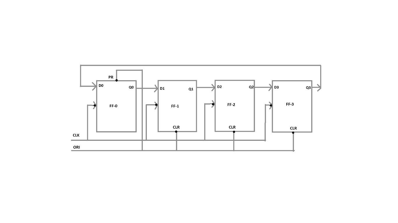
In the block diagram of a ring counter:
- The number of states used is 4, which corresponds to the number of flip-flops employed.
- The pre-set or clear inputs play a vital role in modifying the output values when the input clock signal changes.
The connections in a ring counter are as follows:
- One input is connected to the first flip-flop (ff0-Q0).
- Another input is connected to the CLR (Clear) input of the other three flip-flops (ff1, ff2, ff3).
Truth Table
| ORI | CLK | Q0 | Q1 | Q2 | Q3 |
| Low Pulse | X | 1 | 0 | 0 | 0 |
| 1 | 0 | 0 | 1 | 0 | 0 |
| 1 | 0 | 0 | 0 | 1 | 0 |
| 1 | 0 | 0 | 0 | 0 | 1 |
| 1 | 0 | 1 | 0 | 0 | 0 |
In the truth table, the clock (CLK) and ORI (input) are considered, while the outputs Q0, Q1, Q2, and Q3 correspond to the four flip-flops. The table demonstrates the shifting behavior of ‘1’ diagonally from Q0 to Q3, and then back to Q0. This behavior of the ring counter effectively functions as a ring, hence the name.
Advantages of Ring Counter
- The ring counter can encode and decode logic, allowing for versatile applications.
- Implementation of the ring counter can be achieved using both JK and D flip flops.
Disadvantages of Ring Counter
- Only 4 out of 15 states are utilized in the ring counter, resulting in limited utilization of available states.
- The ring counter is non-self-starting, meaning it requires external intervention to initialize the counter.
Applications of Ring Counter
- Frequency counters
- Analog-to-digital converters (ADC)
- Digital clocks
- Measurement timers and rate calculators, among others.
FAQs:
What does SISO shift register mean?
SISO shift register stands for Serial In, Serial Out shift register. It processes input data and output data serially, storing the results in the register one after another.
What is an asynchronous counter?
An asynchronous counter operates independently of clock pulses, and it typically has 2n – 1 states.
What is the modulus of a counter?
The modulus of a counter refers to the number of states it possesses. It is also known as a mod counter.
What is a divide-by-N counter?
A divide-by-N counter refers to the division of the input clock frequency by N.
How many states are there in a 10-bit ring counter?
A 10-bit ring counter utilizes 10 states.
Related topics