
Understanding Voltage Drop in DC Circuits
In a direct-current (DC) circuit, the concept of voltage drop is crucial for understanding how energy is distributed among various components. Let’s explore the factors influencing voltage drop, the role of resistance in conductors and resistors, and how we use Ohm’s Law and Kirchhoff’s Circuit Laws to analyze voltage distribution.
Components in a DC Circuit
Imagine a DC circuit with a nine-volt DC source, three resistors (67 ohms, 100 ohms, and 470 ohms), and a light bulb, all connected in series. Each component, including the DC source, conductors (wires), resistors, and the light bulb, has a certain resistance that causes the supplied energy to dissipate to varying degrees.
Understanding DC Resistance in Conductors
The resistance of a conductor in a DC circuit depends on its length, cross-sectional area, material type, and temperature. As current flows from the DC source to the first resistor (67 ohms), some energy is lost due to the resistance of the wire. Consequently, the voltage at the first resistor will be slightly less than the nine volts supplied by the DC source.
Voltage Drop Across Resistors
In the circuit, voltage drops occur in both the supply wire and the return wire. When you measure the voltage drop across each resistor, you’ll observe significant values. This voltage drop represents the energy consumed by the resistor. The larger the resistor’s value, the more energy it consumes, resulting in a larger drop across that specific resistor.
Ohm’s Law and its Application
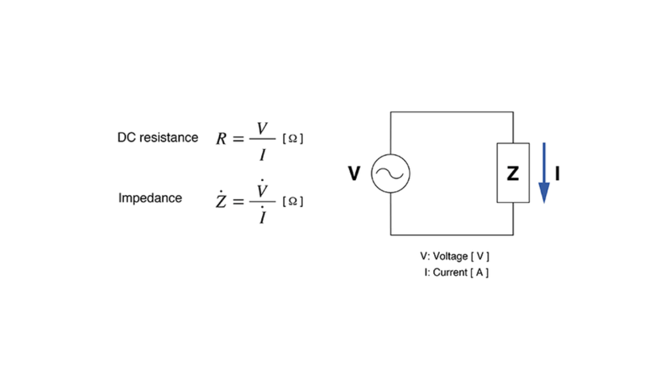
Ohm’s Law states that voltage (V) equals current (I) multiplied by resistance (R), or V=IRV = IRV=IR. This law is instrumental in verifying the voltage drop across resistors. It provides a fundamental relationship between voltage, current, and resistance, enabling us to analyze and understand the behavior of electrical circuits.
Kirchhoff’s Circuit Laws for Energy Conservation
Kirchhoff’s circuit laws are vital in any DC circuit. They state that the sum of the voltage drops across each component is equal to the supply voltage, ensuring the conservation of energy within the circuit. By applying Kirchhoff’s laws, we can validate the correctness of our circuit analysis and ensure that energy is appropriately distributed throughout the circuit.
Conclusion
Voltage drop is a critical aspect of understanding the distribution of energy in a direct-current (DC) circuit. The resistance in conductors and resistors leads to energy dissipation, resulting in voltage drops across various components. Ohm’s Law allows us to verify these voltage drops and gain insights into the behavior of the circuit. Meanwhile, Kirchhoff’s Circuit Laws ensure energy conservation within the circuit, confirming the accuracy of our analysis. By understanding voltage drop and its related principles, we can design and optimize efficient DC circuits for various applications.