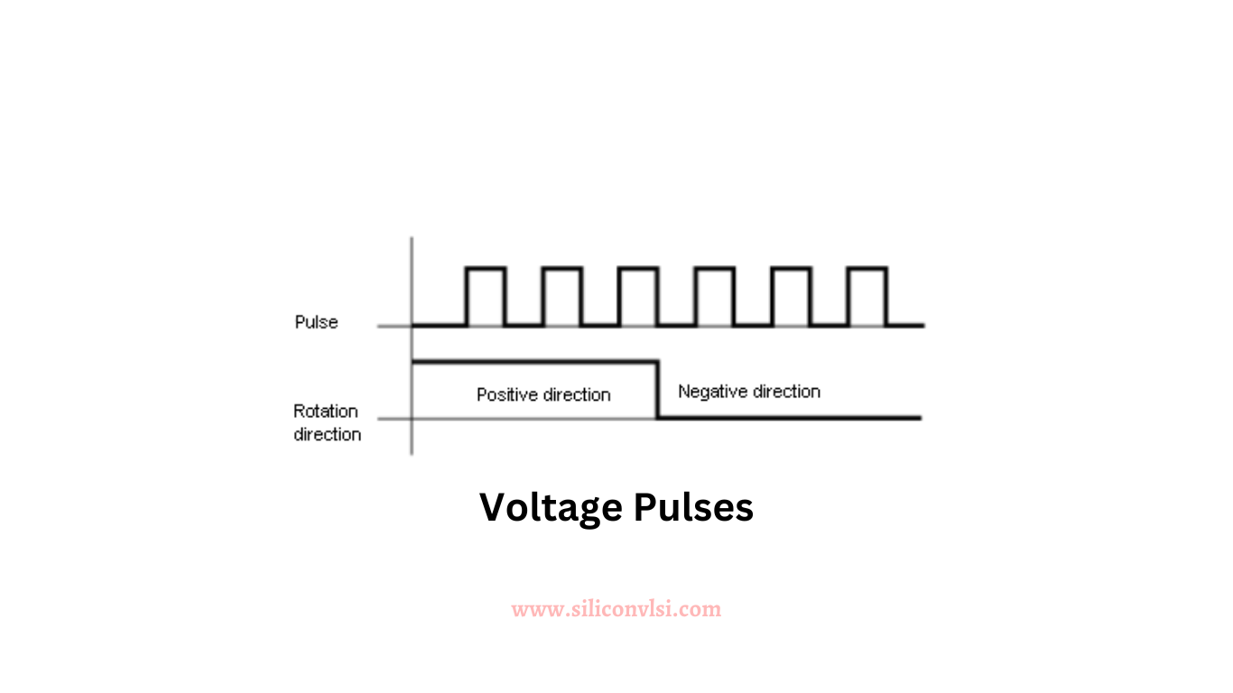
Voltage Pulses on Power Lines
Voltage spikes or short pulses are frequent occurrences on power lines, varying in duration and amplitude and capable of manifesting at any point in the power cycle. These pulses can originate from power and load switching, posing a risk of hardware damage and errors in digital processes. Electrostatic discharges or lightning strokes can also generate such pulses, extending beyond power lines. A voltage pulse introduces a changing E (electric) and H (magnetic) field, which can cross-couple to affect other circuits.

Mathematical Representation of Voltage Pulses
A voltage pulse, as a singular electrical event, possesses characteristics such as rise time, fall time, amplitude, and duration. Unlike repetitive waveforms that allow harmonic analysis, single events necessitate a different approach. Mathematically, a single voltage pulse can be represented by adding sine waves at all frequencies with amplitude and phase relationships. This sophisticated mathematical representation helps us understand the pulse generation process.
Circuit Response to Voltage Pulses
Analyzing the actual response of a circuit to a single pulse is complex, and typically, the focus is on determining the peak amplitude of the response rather than the detailed waveform. To simplify the analysis, substituting a continuous sine wave for the pulse provides an approximation of the amplitude response. The selected frequency is determined by the pulse’s rise time, and the peak amplitude of the sine wave corresponds to the voltage difference between the 10% and 90% points of the pulse.
Rise-Time Approach and Safety Factor
This rise-time approach is not limited to pulses but extends to analyzing the maximum response to any repetitive waveform. The shortest rise or fall time determines the frequency, and the peak amplitude of the sine wave indicates the circuit or system’s response to the initial waveform. Although this method may seem crude, it offers valuable insight into a challenging problem. The analysis inherently incorporates a safety factor, prioritizing conservative design choices. For instance, if circuit damage occurs at 6 V, designing for a much lower peak response, such as 0.6 V, provides a safe margin in critical designs.