
Hardware Description Languages (HDLs): 7 Essential Concepts You Should Know
Hardware Description Languages (HDLs) are text-based languages used to describe digital electronic systems. Instead of drawing every circuit connection manually, designers can use HDL code to describe how a circuit should behave and how its components are connected[1].
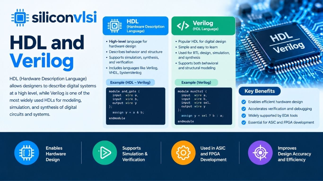
The two widely used HDLs in digital system design are VHDL and Verilog. These languages are used for designing, simulating, verifying, and synthesizing digital hardware, from simple logic circuits to complex processors and SoCs.
What Are Hardware Description Languages?
An HDL provides a way to represent hardware using text. A designer can describe the functionality, data movement, or structure of a digital circuit and then use EDA tools to simulate or synthesize the design.
HDLs are useful because the same design description can be:
- Simulated before hardware is built
- Verified using testbenches
- Synthesized into digital logic
- Modified and reused more easily
- Documented as part of the design
- Developed using a structured top-down methodology
This makes HDLs an important part of modern digital VLSI design.
What Is Verilog?
Verilog is a hardware description language used to model and design digital systems. It can describe both simple logic circuits and large digital systems.
Verilog was originally developed by Gateway Design Automation in the 1980s. It later became an open and standardized language, with industry organizations contributing to its standardization and the language eventually becoming an IEEE standard.
One reason Verilog became popular is its relatively compact syntax and its similarities to the C programming language. However, Verilog is a hardware description language, not a general-purpose software programming language. Its constructs are intended to represent hardware behavior and structure.
Verilog can be used to describe:
- Combinational logic
- Sequential logic
- Registers and flip-flops
- Finite-state machines
- Datapaths
- Control logic
- Larger digital systems
Different HDL Description Levels
An HDL can describe hardware at different abstraction levels. The three commonly discussed descriptions are behavioral, dataflow, and structural.
Behavioral Description
Behavioral modeling describes what the circuit should do without necessarily specifying every gate used to implement it.
For example, a designer can describe an arithmetic operation without manually drawing every logic gate required to perform that operation.
Dataflow Description
Dataflow modeling describes how data moves through logic and how outputs are related to inputs using expressions and operators.
For example:
Y = A & B
This describes the logical relationship between the input signals and the output.
Structural Description
Structural modeling describes the hardware in terms of components and their connections.
For example, a design can be represented using:
- Logic gates
- Modules
- Components
- Signal connections
These different abstraction levels allow designers to choose an appropriate level of detail for a particular design task.
HDL and Top-Down Design
HDLs support a top-down design methodology. Instead of starting with individual gates, designers can begin with the overall system and gradually divide it into smaller blocks.
A simplified process looks like this:
System Specification → Architecture → RTL Design → Simulation → Synthesis → Gate-Level Design → Physical Implementation
For example, a processor can first be divided into major blocks such as the control unit, ALU, registers, and memory interface. Each block can then be described and verified separately.
This approach makes large digital designs easier to develop, test, modify, and maintain.
VHDL vs Verilog
VHDL and Verilog are both hardware description languages used for digital system design. They provide different syntax and language features, but both can be used to describe synthesizable digital hardware.
| Feature | VHDL | Verilog |
|---|---|---|
| Language type | Hardware Description Language | Hardware Description Language |
| Syntax influence | Ada | C |
| Design modeling | Behavioral, dataflow, structural | Behavioral, dataflow, structural |
| Readability | More verbose and strongly typed | More compact |
| Large system documentation | Often valued for explicitness | Also suitable for large designs |
| Hardware synthesis | Supported | Supported |
| Simulation | Supported | Supported |
| Common use | RTL design and verification | RTL design and verification |
The choice between VHDL and Verilog often depends on the organization, existing design environment, project requirements, and designer experience.
It is better to avoid treating one language as universally better for synthesis or the other as universally better for simulation. Both VHDL and Verilog can be used for RTL design, simulation, and synthesis.
Verilog and System-Level Design Languages
HDLs are not the only languages used in hardware development. System-level languages such as SystemC can be used to model larger systems and hardware/software interactions at a higher level of abstraction.
These approaches can help engineers explore system architecture before committing to detailed RTL implementation.
For large projects, system-level modeling can also help different engineering teams communicate and identify architectural problems earlier in the development process.
Why Are HDLs Important in VLSI Design?
HDLs have become an important part of modern VLSI design because manually creating and modifying large digital circuits becomes difficult as circuit complexity increases.
With HDL-based design, engineers can:
- Describe hardware using reusable source code.
- Simulate the design before fabrication.
- Create testbenches for functional verification.
- Synthesize RTL into a gate-level implementation.
- Modify designs without manually redrawing complete schematics.
- Reuse modules across different projects.
- Develop large digital systems using hierarchical design.
For this reason, knowledge of HDL programming is particularly important for engineers working in RTL design, digital VLSI, FPGA development, ASIC design, and verification.
Verilog, VHDL, and Modern HDL Design
Verilog and VHDL remain important HDL technologies, while newer languages and extensions have also become part of modern hardware development.
For example, SystemVerilog extends Verilog with additional RTL and verification capabilities. It provides features such as interfaces, assertions, improved data types, constrained-random verification, and object-oriented constructs for verification.
A typical modern digital design flow may therefore involve:
System Specification → System-Level Modeling → RTL Design → Functional Verification → Synthesis → Physical Design → Signoff
The exact flow depends on the project and technology.
Common Questions About Hardware Description Languages
What are the two popular hardware description languages?
Two widely used HDLs are VHDL and Verilog. Both can be used to describe, simulate, and synthesize digital hardware.
Why are text-based HDLs useful?
Text-based HDLs provide a structured way to describe and document digital circuits. They also allow EDA tools to simulate and synthesize the design, making them practical for large and complex systems.
Who developed Verilog?
Verilog was originally developed by Gateway Design Automation in the 1980s. It later evolved into an open and standardized language and became an IEEE-standardized HDL.
What are the main HDL description levels?
Common abstraction levels include behavioral, dataflow, and structural modeling.
- Behavioral: describes what the circuit does.
- Dataflow: describes relationships and movement of data using expressions.
- Structural: describes components and their interconnections.
What is the advantage of HDL in a top-down design approach?
HDLs allow designers to start with a high-level system description and progressively refine it into smaller modules and eventually hardware that can be synthesized.
What are the roots of Verilog and VHDL syntax?
Verilog has syntax influenced by C, while VHDL has roots influenced by Ada. Their syntax and language structures are different, but both are designed specifically for describing digital hardware.
Is Verilog better than VHDL?
There is no universal answer that one is better for every project. Both can be used for RTL design, simulation, verification, and synthesis. The appropriate choice depends on project requirements, existing tools, coding standards, and team experience.
Conclusion
Hardware Description Languages (HDLs) provide a practical way to describe digital hardware using text rather than relying entirely on graphical schematics. Verilog and VHDL are two important HDLs used throughout digital design and VLSI development.
HDLs support different abstraction levels, including behavioral, dataflow, and structural descriptions. They also fit naturally into a top-down design methodology, allowing engineers to move from system-level concepts toward detailed RTL and synthesized hardware.
For anyone learning digital VLSI, RTL design, ASIC design, FPGA development, or hardware verification, understanding HDL fundamentals is an important starting point.
References
- S. Shiva, “Computer hardware description languages—A tutorial”, Proceedings of the IEEE, vol. 67, no. 12, pp. 1605–1615, 1979, doi: 10.1109/proc.1979.11541.