

Voltage-Aware DRC (VA-DRC): 7 Essential Concepts for Reliable Signoff
As semiconductor designs become denser and increasingly use multiple voltage domains, traditional geometric Design Rule Checking (DRC) becomes more challenging.
Conventional metal-spacing rules are often based only on physical geometry. However, in some advanced and high-voltage designs, the required spacing can also depend on the voltage present on a net or the voltage difference between neighboring nets.
This requirement leads to Voltage-Aware Design Rule Checking (VA-DRC).
VA-DRC combines physical layout information with voltage information so that the appropriate spacing rule can be applied to different nets. For this methodology to work correctly, the DRC flow needs reliable voltage information for the layout.
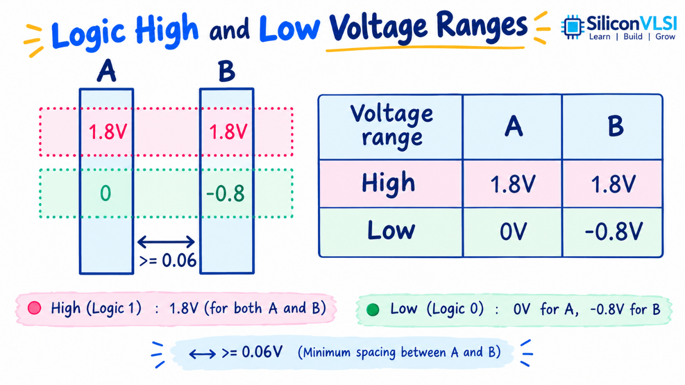
What is Voltage marker DRC?
Voltage marker DRC is a design-rule checking methodology in which some physical design rules depend on electrical voltage information.
In a conventional DRC flow, a spacing rule might simply specify a minimum distance between two geometries.
With VA-DRC, the required spacing can vary according to factors such as:
- Voltage on the first net
- Voltage on the second net
- Voltage difference between neighboring nets
- Technology-specific reliability requirements
- Geometry and layer information
A simplified concept is:
Geometry + Connectivity + Voltage Information → Appropriate DRC Rule
This makes VA-DRC particularly useful for designs containing multiple power domains, high-voltage signals, and complex voltage interactions.
Why Is VA-DRC Needed?
As process technologies and IC designs become more complex, a single spacing value may not adequately represent every electrical situation.
For example, two neighboring metal lines operating at relatively similar voltages may have different spacing requirements from two lines with a large voltage difference.
Therefore, the DRC system may need to understand not only:
“How close are these two geometries?”
but also:
“What voltages are present on these two nets?”
This adds an electrical dimension to what was traditionally a primarily geometric verification problem.
1. Voltage Information Must Be Accurate
VA-DRC depends heavily on accurate voltage information.
If the DRC tool receives an incorrect voltage value, it may apply an inappropriate spacing rule.
This can lead to:
- False DRC violations
- Missing or incorrect violations
- Difficult debugging
- Unnecessary design changes
- Additional signoff effort
For this reason, voltage information must be consistent with the actual design connectivity and intended operating conditions.
2. Manual Voltage Annotation Can Be Error-Prone
One traditional approach is to manually add voltage markers or text annotations to the layout.
For example, a designer may place text indicating:
1.8 V
or
3.3 V
on the appropriate net.
Although this approach can work for smaller designs, manually creating a large number of annotations becomes difficult as the design grows.
Potential problems include:
- Missing annotations
- Incorrect voltage values
- Duplicate annotations
- Conflicting voltage values
- Incorrect hierarchy
- Human errors during editing
A small annotation error can potentially result in a large number of confusing DRC results.
3. Voltage Annotation Conflicts
Multiple voltage annotations can sometimes exist for the same net, particularly in large hierarchical designs containing multiple IP blocks.
Consider a net with several voltage annotations:
- Annotation A: 1.8 V
- Annotation B: 1.8 V
- Annotation C: 3.3 V
The conflicting 3.3 V annotation needs to be identified and corrected before relying on the voltage-aware verification results.
A useful automated check can identify such text collisions or conflicting annotations before voltage propagation is performed.
This type of verification can help designers find inconsistent voltage information before it creates additional DRC debugging problems.
4. Voltage Propagation Helps Automate the Process
A more automated VA-DRC methodology can determine voltage information from the design’s connectivity rather than requiring every net to be manually annotated.
A simplified flow is:
Supply Voltage → Voltage Propagation → Internal Nets → Voltage Annotation → VA-DRC
The voltage propagation process uses connectivity and defined propagation rules to determine the expected voltage associated with internal nodes.
This approach can significantly reduce the amount of manual annotation required in large designs.
Figure 3: Automated voltage annotation and VA-DRC flow.
The source material describes Calibre PERC as an example of a reliability-verification platform that can perform voltage propagation and generate voltage annotations for use with Calibre nmDRC.
These are examples of commercial verification tools; the exact implementation depends on the foundry rules, tool flow, and design environment.
5. Automated Text Annotation Reduces Human Error
Automated annotation can generate voltage text based on the calculated voltage information.
The generated information can then be provided to the DRC flow so that the appropriate voltage-aware rules can be applied.
The major advantage is that designers do not have to manually place voltage markers throughout the entire design.
Automation can help:
- Reduce manual work
- Improve annotation consistency
- Detect conflicting information
- Handle large hierarchical designs
- Improve verification turnaround
- Make debugging more systematic
The automation approach is especially useful when a design contains many voltage domains and a large number of internal nets.
6. Debugging Requires Both Physical and Electrical Information
VA-DRC debugging can be more complicated than conventional geometric DRC because the cause of a violation may involve both physical layout and electrical connectivity.
For example, a designer may need to determine:
- Which two geometries caused the violation?
- Which nets are involved?
- What voltage is assigned to each net?
- Where did that voltage originate?
- Why was a particular spacing rule applied?
An effective debugging environment should therefore provide both geometric and connectivity-based information.
Voltage tracing can also help designers follow an internal node back toward its voltage source or origin.
7. VA-DRC Is Important for Multi-Voltage Designs
Modern ICs frequently contain multiple voltage domains. Different blocks may operate at different supply voltages depending on their function and technology requirements.
Examples can include:
- Core logic
- I/O circuits
- Analog blocks
- High-voltage interfaces
- Memory circuits
- Power-management circuitry
As the number of voltage domains increases, understanding the voltage associated with each physical net becomes increasingly important for voltage-dependent design rules.
VA-DRC provides a way to connect this electrical information with physical verification.
VA-DRC vs Conventional DRC
| Feature | Conventional DRC | Voltage-Aware DRC |
|---|---|---|
| Primary information | Geometry | Geometry + voltage/connectivity |
| Spacing rules | Usually geometry-based | Can depend on voltage |
| Voltage information | Generally not required | Required for applicable rules |
| Multiple voltage domains | Less relevant to basic spacing checks | Important |
| Annotation | Usually unnecessary for standard spacing | May be required or automatically generated |
| Debugging | Mainly physical | Physical + electrical/connectivity |
| Complexity | Lower | Higher |
Manual vs Automated Voltage Annotation
| Aspect | Manual Annotation | Automated Annotation |
|---|---|---|
| Annotation effort | High for large designs | Reduced |
| Human error | More likely | Lower when flow is correctly configured |
| Large hierarchical designs | Difficult to manage | Better suited |
| Conflict detection | Requires additional checking | Can be automated |
| Voltage propagation | Usually manually defined | Can be calculated from connectivity |
| Debugging | More difficult | Can provide voltage tracing and context |
Why Voltage Accuracy Matters in DRC Signoff
Signoff DRC is performed before tapeout, so incorrect voltage information can create unnecessary risk late in the design cycle.
Incorrect annotations may cause the DRC engine to evaluate a net using the wrong voltage-dependent rule.
This can result in a large number of violations that are difficult to distinguish from genuine physical-design problems.
Therefore, a robust VA-DRC flow should provide:
- Accurate voltage information
- Consistent annotation
- Conflict detection
- Connectivity-aware voltage propagation
- Traceable debugging results
- Integration with the signoff DRC flow
Typical Voltage-Aware DRC Flow
A simplified VA-DRC flow can be represented as:
1. Identify Supply Voltages
↓
2. Analyze Design Connectivity
↓
3. Propagate Voltage Information
↓
4. Generate or Validate Voltage Annotations
↓
5. Run Voltage-Aware DRC
↓
6. Debug Geometric and Electrical Results
↓
7. Fix and Re-run Signoff
This flow reduces dependence on manually created voltage markers and provides a more systematic way to handle voltage-dependent spacing rules.
Common Challenges in VA-DRC
Several challenges need to be considered when implementing voltage-aware verification.
Large Design Size
A modern SoC can contain millions or billions of geometries and many voltage domains. Manual annotation does not scale efficiently.
Hierarchical IP
Different IP blocks may contain their own voltage information, creating potential conflicts when they are integrated into the top-level design.
Incorrect Voltage Values
An incorrect annotation can cause the DRC engine to apply the wrong rule.
Debugging Complexity
A violation may depend on both geometry and electrical connectivity, making debugging more involved than a simple spacing violation.
Verification Runtime
The additional connectivity and voltage analysis can increase verification complexity and runtime depending on the implementation.
Key Takeaways
The most important points about Voltage-Aware DRC (VA-DRC) are:
- VA-DRC applies spacing or other design rules using voltage information in addition to geometry.
- It becomes important when designs contain multiple voltage domains or voltage-dependent reliability requirements.
- Manual voltage annotation can be time-consuming and prone to errors.
- Conflicting voltage annotations can create confusing or false DRC results.
- Voltage propagation can automate the determination of voltage information for internal nets.
- Effective debugging requires both physical layout and electrical connectivity information.
- Automated VA-DRC flows can improve verification consistency and reduce manual effort.
Frequently Asked Questions
What is VA-DRC in VLSI?
VA-DRC, or Voltage-Aware Design Rule Checking, is a DRC methodology in which certain design rules depend on the voltage associated with a net or the voltage difference between nets.
Why is voltage information required for VA-DRC?
Some spacing and reliability rules can vary according to the electrical conditions of the nets. Therefore, the DRC tool needs accurate voltage information to select and apply the appropriate rule.
What is voltage annotation?
Voltage annotation is information associated with a layout net that identifies its voltage value for use during voltage-aware verification.
Why can manual voltage annotation be problematic?
Large designs can contain thousands or millions of relevant nets. Manually assigning voltage information increases the possibility of missing, duplicated, or conflicting annotations.
What is voltage propagation?
Voltage propagation is a connectivity-based method for determining the voltage associated with internal nodes from known supply or source voltages according to defined propagation rules.
Is VA-DRC only useful for advanced process nodes?
No. VA-DRC can be useful wherever design rules depend on voltage, including designs with multiple power domains or high-voltage circuitry. The exact requirements depend on the technology and foundry rules.
Conclusion
Voltage-Aware DRC (VA-DRC) extends traditional physical verification by incorporating electrical voltage information into applicable design-rule checks.
As ICs become denser and increasingly incorporate multiple voltage domains, manually assigning voltage information throughout a large hierarchical layout becomes difficult and error-prone.
An automated flow can propagate voltage information through the design, identify conflicting annotations, generate the information required by the DRC process, and provide context-aware debugging.
The result is a more systematic approach to voltage-dependent spacing verification and can help designers achieve reliable DRC signoff within demanding tapeout schedules.