Understanding Voltage Drop in AC Circuits: A Student’s Guide
Voltage drop is the reduction in electrical potential in a circuit’s path, and it happens because of the resistance and reactance present in wires and components. When current flows through a conductor, some energy is naturally lost due to these factors, causing a decrease in voltage as it travels further from the power source.

Components of Electrical Impedance
Electrical impedance is determined by the vector sum of three components:
Electrical Resistance: Just like in DC circuits, electrical resistance restricts the flow of current in an AC circuit.
Capacitive Reactance: AC circuits with capacitors exhibit capacitive reactance, which opposes changes in voltage over time.
Inductive Reactance: AC circuits with inductors experience inductive reactance, which opposes changes in current flow.
Calculation of Electrical Impedance
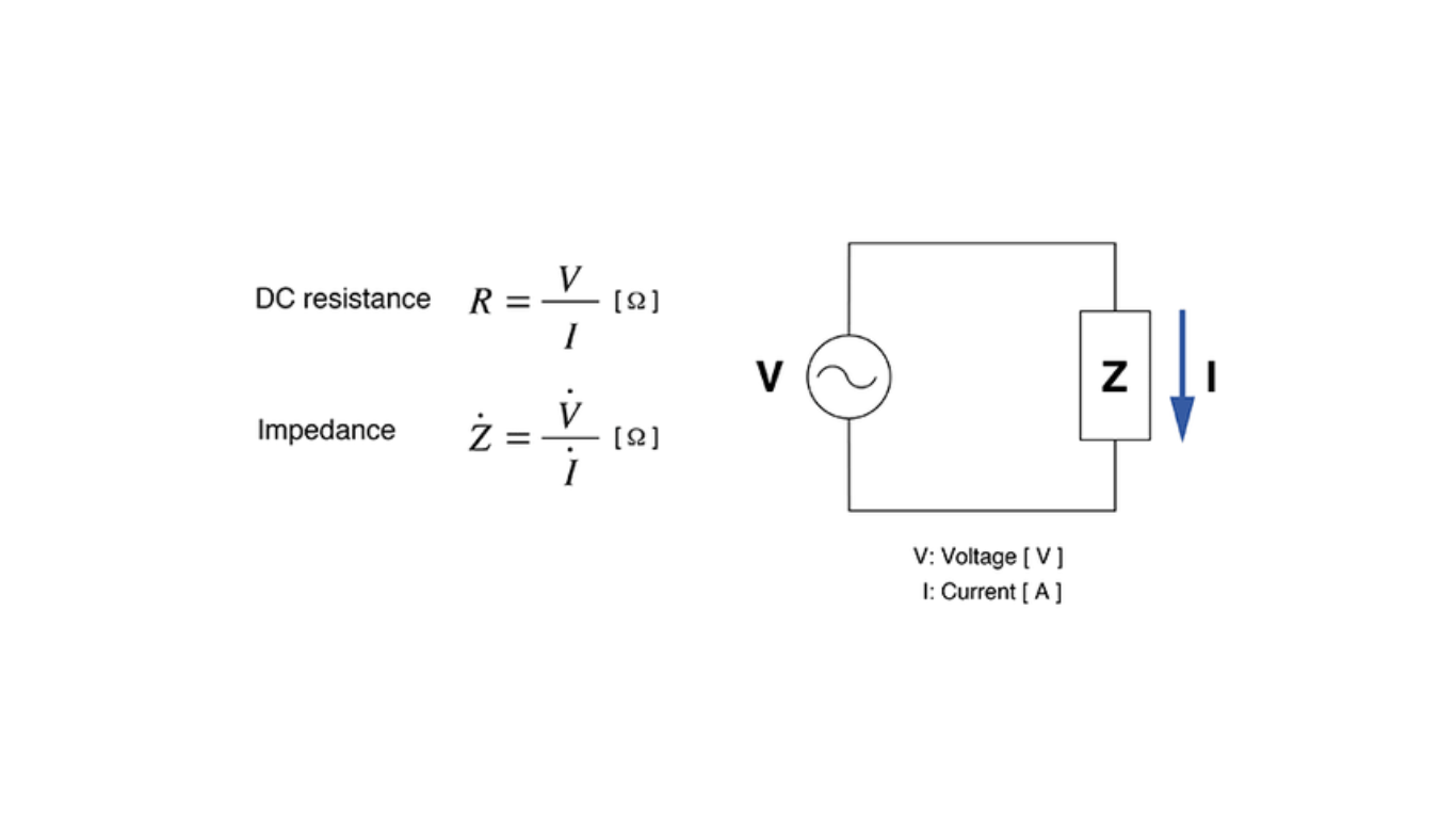
Electrical impedance (Z) is computed as the vector sum of electrical resistance (R), capacitive reactance (Xc), and inductive reactance (Xl):
Electrical Impedance (Z) = R + Xc – Xl
Voltage Drop Calculations – Engineers Edge
Analogous to Ohm’s Law
Analogous to Ohm’s law in DC circuits, the relationship between voltage (E), current (I), and electrical impedance (Z) in AC circuits is expressed by the formula E = I Z. This equation indicates that the voltage drop (E) in an AC circuit is the product of the current (I) and the impedance (Z) of the circuit.
Conclusion
In AC circuits, impedance plays an important role as the combined opposition to current flow from resistance, capacitive reactance, and inductive reactance. When we understand impedance, we can design and analyze AC circuits more effectively, ensuring optimal performance and power delivery in various electrical applications.