
In a CMOS (Complementary Metal-Oxide-Semiconductor) inverter, the type of current flowing in the source and drain regions depends on whether you’re referring to the PMOS (p-channel) or NMOS (n-channel) transistor within the inverter.
Hole and Electrons Current
For the PMOS (p-channel) transistor:
In the source region: You will find holes (positive charge carriers) carrying the current. In the drain region: You will also find holes (positive charge carriers) carrying the current.
For the NMOS (n-channel) transistor:
In the source region: You will find electrons (negative charge carriers) carrying the current. In the drain region: You will also find electrons (negative charge carriers) carrying the current.
CMOS inverters use a combination of both PMOS and NMOS transistors to efficiently switch between high and low logic states, making them a fundamental building block in digital integrated circuits.
Idc and Irms Current
In a CMOS inverter, you will primarily find two types of currents:
DC Current (Ids or Iaverage): This current represents the average or direct current flowing through the transistors when they are in the on or off state, depending on the logic level. It is the steady-state current that represents the power consumption of the CMOS circuit.
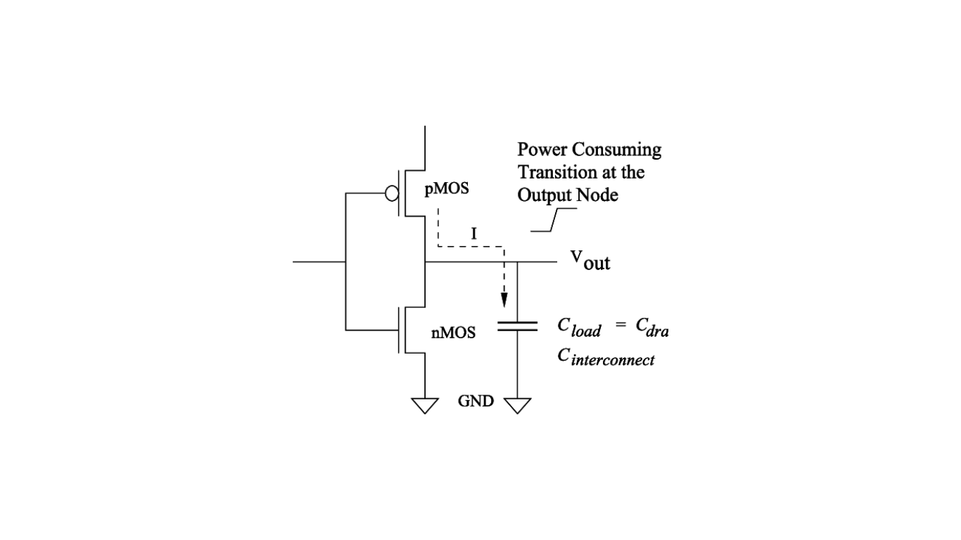
AC Current (Irms): In a dynamic CMOS circuit, there’s also an AC current component, typically associated with the transient charging and discharging of capacitive loads when the transistors switch between states. This AC current is characterized by its root mean square (Irms) value, which takes into account the current fluctuations over time.
The Irms value is particularly important when considering power dissipation and dynamic power consumption in CMOS circuits, as it accounts for the current variations during switching events. However, the Irms and Ids/Average values are interconnected, as the AC component adds to the DC current during switching.
The DC current is the primary contributor to power dissipation in CMOS circuits, while the AC current, represented by Irms, occurs during brief switching periods and is relatively smaller in magnitude.