
Physical Verification
There are four main types of physical verification checks in the VLSI layout design. for example, LVS (layout vs schematic), DRC (design rule constraint check), LEC (logical equivalence check & ERC (electric rule check). Let’s see all checks in detail
LVS (Layout vs Schematic)
LVS tools are frequently used in conjunction with parasitic extraction tools for electrical rule testing, measurement of device stress metrics (particularly at 40 nm and below), and interactive corrections to speed up error debugging. By offering device and connection comparisons between the IC layout and the schematic, a layout vs. schematic (LVS) physical verification tool serves an important purpose as a component of a whole IC verification tool suite.
Because it can measure actual device geometries over the entire chip for an exhaustive accounting of physical properties, an LVS tool offers precise circuit verification. The measured device parameters provide thorough data for running simulations as well as information for back-annotation to the original schematic.
How does LVS work?
The LVS flow is composed of two basic components. Extraction is the initial step in the flow, during which all of the devices and nets are extracted after an analysis of the layers in the layout database. The real comparison of devices and nets takes place during the compare procedure, which is the second step in the flow.
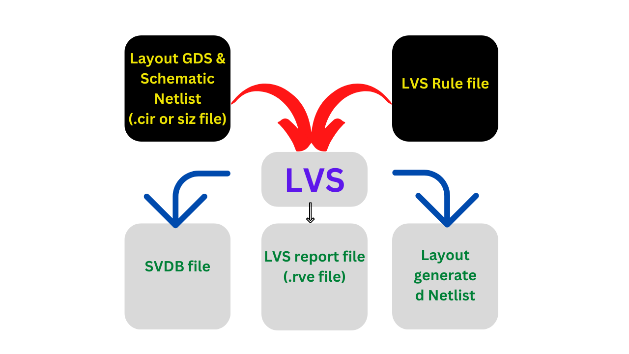
LVS Input file
- Layout GDS
- LVS rule file
- Schematic Netlist(.siz file or .cir file)
LVS Output file
- LVS summary report file
- SVDB file(ERC summary)
- Layout generated Netlist
List of LVS errors.
There are main two types of LVS errors.
Extraction Errors
- Floating text
- open text
- short text
- Extraction error
- Stamping Conflict in CONNECT
LVS error
- Open- short LVS
- Device mitch match error
- Property errors
- Port swap errors
- Unmatched nets in the layout/schematic
- Unmatched devices in the layout/schematic
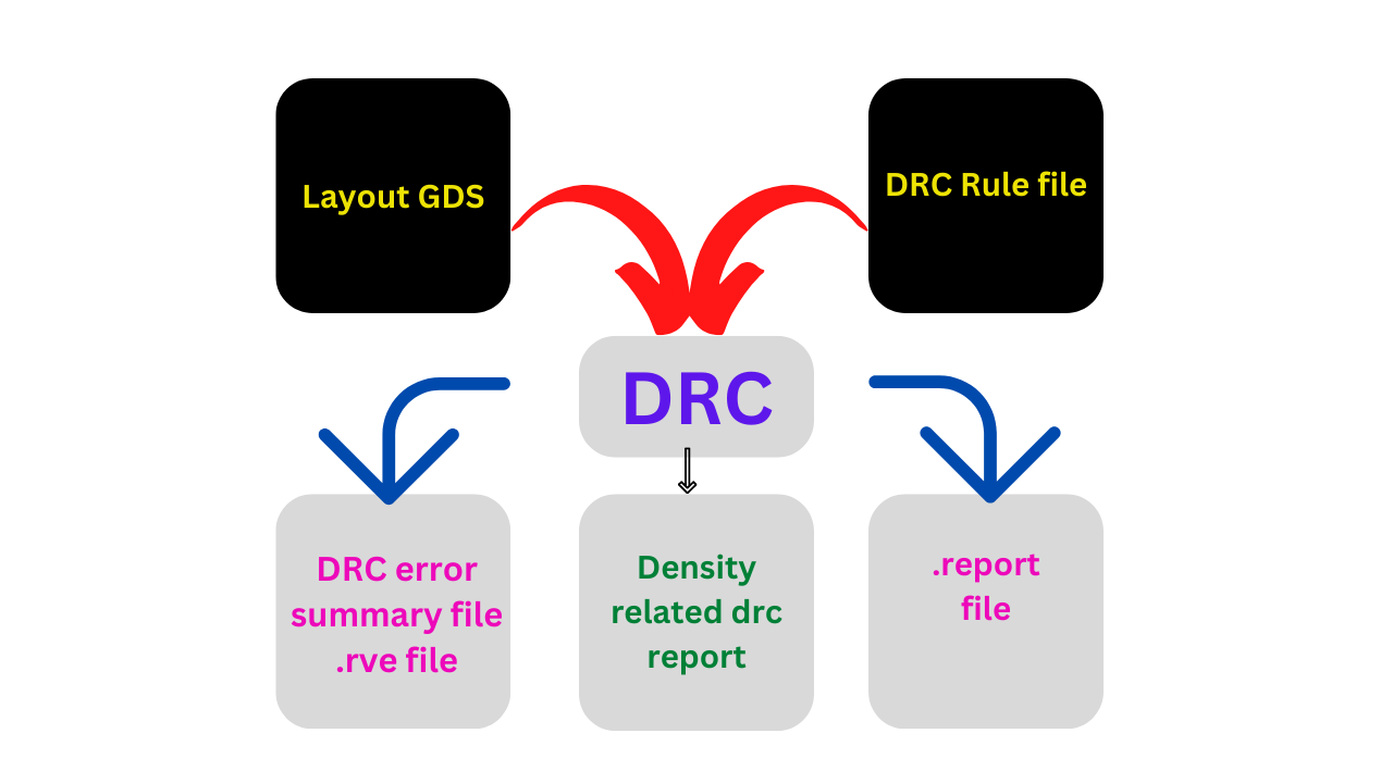
DRC (Design Rule Constrain check)
A physical design technique called Design Rule Checking (DRC) is used to check whether a chip layout complies with a number of requirements set out by the semiconductor manufacturer. Each semiconductor manufacturing process will have its own set of guidelines and margins to ensure that normal manufacturing variability won’t lead to chip failure.
Types of DRC checks
- Minimum width
- Minimum area
- Minimum spacing
- Wide metal jog
- Maximum width
- Misaligned via wire
- Stack via
- Wide via
- Via spacing
- Special notch spacing
- End-of-line spacing
ERC(Electrical rule checking )
Electrical rule checking (ERC) is a methodology used to assess a design’s resilience against several “electronic design rules” at both the schematic and layout levels. These design guidelines are frequently project-specific and created in response to lessons learned from past tape-outs or in advance of probable future failures.
Design robustness is unquestionably degraded when ERC is not enforced, as failures in the field can be delayed, defect escapes to consumers can occur, and yield can be lowered.
List of ERC checks
- Soft check error
- Floating devices
- Floating taps
- Floating well
- Gate connection to direct with power.
- Antenna Rule
Logic equivalence checking (LEC)
By examining the combinatorial structure of the design, logic equivalence checking (LEC) ascertains whether the structures of two different implementations will display the same behavior. The structure of a design will no longer transfer between the two representations if procedures like retiming are done to it.
What is ERC in physical verification?
An Electrical Rule Check (ERC) is a crucial step in the design process of integrated circuits, ensuring their proper functionality. ERC tools are capable of detecting potential circuit errors that could result in decreased yields or circuit malfunctions post-delivery. By performing an ERC, designers ensure that the printed circuit boards (PCBs) meet the requirements for functionality, reliability, and manufacturability, thus enhancing the overall quality of the electronic devices.