
VLSI Physical Design Flow is the process of converting synthesized netlist, design curtailment, and standard library to a layout as per the design rules. Let’s discuss blockages and halo
Blockage in VLSI
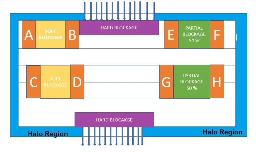
Blockages are places where the placement of cells is restricted or blocked. They serve as guidance for placing standard cells in the design. Blockages prevent the placement tool from placing standard cells at designated locations even though they won’t be guiding it to do so.
Types of Blockages
- Soft ( Non-Buffer ) Blockage
- Hard ( std cell) Blockage
Soft Blockage
Soft Blockage specifies a region where only buffers can be placed. That means standard cells cannot be placed in this region. It blocks the placement tool from placing non-buffer cells such as standard cells in this region.
Often, soft obstructions are used to direct placement and routing tools toward a desired layout or to stop specific components from being placed in undesirable locations.
For instance, a soft blockage may be used to keep noise sources away from delicate components like clock buffers or voltage regulators or to avoid congestion in vital routes when routing. Soft blocks can also be used to make sure that specified parts or signals are positioned near I/O pads or power sources, for example, on the chip.
Partial Blockages
Some percentage of the area is unavailable for placement. When there are competing design objectives or requirements, such as the need to reduce chip size while also making sure that important signals are adequately routed and insulated from noise sources, partial blockages are frequently utilized.
The creation of “keep-out” zones around delicate parts or signals, such as clock buffers or power sources, is one common application of partial blockages. By using these zones to prevent other parts or signals from being positioned too close to the sensitive area, noise coupling can be reduced and overall signal integrity can be improved.
Hard Blockage
Hard blockage specifies a region where all standard cells and buffers cannot be placed. It prevents the placement tool from placing std cells and buffers in this region.
Hard blockages are mostly used to:
- Block std cells to certain regions in the design
- Avoid routing congestion at macro corners
- Control power rail generations at macro corners
HALO in VLSI
HALO or ( Keep-Out Region) is the region around the boundary of fixed macro in the design in which no other macro or std cells can be placed. Halo allows the placement of buffers and inverters in its area.
Halo is similar to a hard blockage, but it has developed into a macro characteristic, thus if we move the macro, the halo will follow. Halo spacing can be adjusted using instructions.
Halo will help avoid congestion near macro because it prevents the placement of any cells nearby. A macro halo can overlap another macro halo.
What is Macro in VLSI?
Macros are IP(Intellectual Properties) that you can use in your design. For example, memories, processor core, serdes, PLL etc. A macro can be a hard or soft macro. Soft macros are not specific to any manufacturing process, while Hard macros are targeted for specific IC manufacturing technology.
Difference between macro and IP in VLSI?
In VLSI (Very Large Scale Integration), “macro” and “IP” (Intellectual Property) are two terms commonly used to refer to different types of pre-designed and pre-verified components that can be integrated into a larger chip design. Here’s the difference between macro and IP in VLSI:
Macro (Cell or Standard Cell)
Customizable Building Block: A macro, also known as a cell or standard cell, is a fundamental building block in VLSI design. It’s a pre-designed and pre-characterized cell that contains a specific logic function or a simple combinational or sequential circuit.
Customizable Parameters: Macros are highly customizable in terms of their size, functionality, and electrical characteristics. Designers can often modify their properties, such as drive strength or fanout, to meet specific requirements.
Used for Logic Functions: Macros are typically used for implementing basic logic functions like AND gates, flip-flops, latches, etc., which are combined to create more complex digital circuits.
Optimized for Area: Macros are optimized for a smaller silicon area, making them suitable for dense and high-performance chip designs.
Library of Cells: Designers have access to a library of standard cell macros provided by semiconductor foundries.
IP (Intellectual Property)
Complete Functional Blocks: IP, or Intellectual Property, refers to pre-designed and pre-verified functional blocks or modules that serve a specific purpose. These can be more complex than macros and are often used to save time and effort when designing complex systems-on-chip (SoCs).
Complex Functions: IP can encompass more complex functions like microprocessors, memory controllers, interface modules (e.g., USB, Ethernet), DSP blocks, and other specialized functions.
Vendor-Specific: IP blocks are often provided by third-party IP vendors or developed in-house by semiconductor companies. These blocks are generally more rigid and less customizable than macros.
Reusability: IP blocks are designed to be reusable across multiple projects and chip designs, saving significant development time and cost.
Verified and Tested: IP blocks are rigorously tested, verified, and characterized by the IP provider to ensure they meet specified functionality and performance criteria.
In summary, macros are smaller, customizable building blocks optimized for logic functions, while IP blocks are larger, pre-designed functional modules with specific purposes, often provided by third-party vendors. The choice between using macros or IP in a VLSI design depends on the specific requirements, complexity, and time-to-market considerations of the project.