
The difference between a clipper and a clamper is how you control the signal. A clipper restricts the output voltage range, whereas a clamper moves the DC level of the output voltage up or down. You’ll notice that they work in opposite ways when it comes to handling waveforms.
Another difference you should know is in the shape of the output waveform. A clipper changes the shape of the signal by cutting off voltage, but a clamper keeps the shape the same and only shifts it up or down. A clipper doesn’t need a capacitor, but you can’t build a clamper without one. The output shape changes in a clipper, but in a clamper, it stays the same.
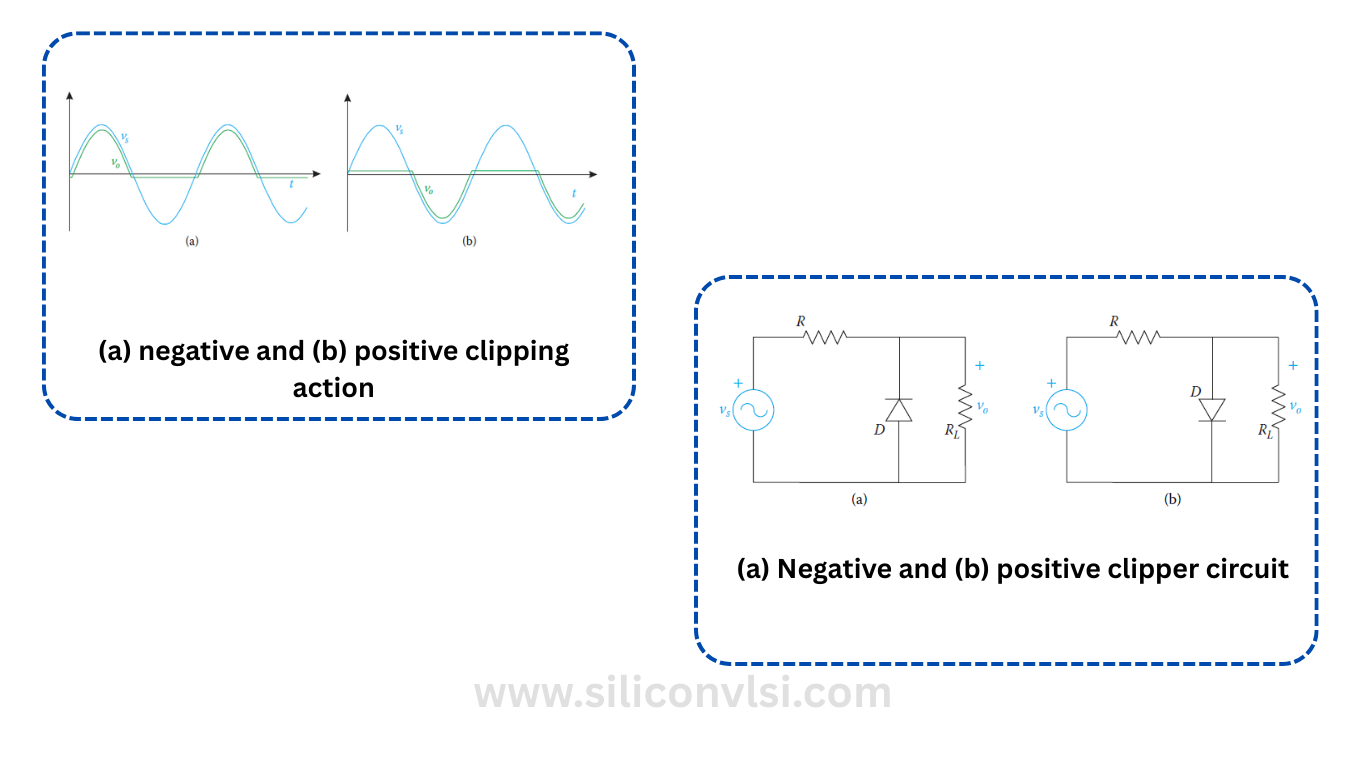
What is a Clipper circuit?
When you use a clipper, you limit the amplitude of the input signal without affecting the rest of it. This helps protect components by making sure excessive voltage doesn’t pass through. You get the voltage to stay within a desired range by clipping off the unwanted part.
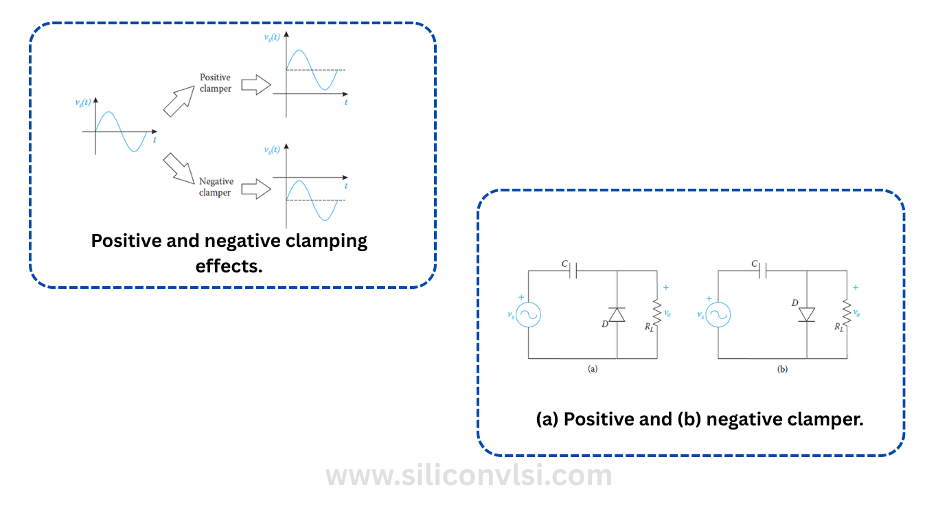
What is a Clamper circuit?
In a clamper, you don’t cut the signal. Instead, you shift the DC level either up or down depending on the type of clamper you use. You need a capacitor, a diode, a resistor, and an AC input to build it. When the negative half cycle enters, the diode conducts and the capacitor charges to its peak value.
Key Differences Between Clipper and Clamper Circuit
If you’re comparing clipper and clamper circuits, you should focus on how each one affects the signal. Below is a simplified table that helps you understand the main differences in how you use and build each circuit.
| Clipper Circuit | Clamper Circuit |
|---|---|
| A clipper is used to remove part of an AC signal. | A clamper is used to shift the DC level of the waveform. |
| A clipper is also called a voltage limiter or slicer. | A clamper is known as a voltage multiplier or DC level shifter. |
| The clipper is built with a diode and a resistor. | A clamper is built with a diode, a resistor, and a capacitor. |
| You don’t need a capacitor in a clipper. | You must use a capacitor in a clamper as it stores energy. |
| A clipper changes the shape of the waveform. | A clamper keeps the waveform shape unchanged. |
| Doesn’t change the DC level of the signal. | Shifts the DC level of the signal. |
| It keeps the signal’s amplitude unchanged. | It shifts the amplitude of the signal. |
| Clipper limits the voltage level of the signal. | A clamper increases the signal’s voltage level. |
| The output voltage is always less than the input. | The output voltage is always more than the input. |
Conclusion
When you want to reduce amplitude, go with a clipper. If you want to shift the DC level, choose a clamper. You’ll find both useful in electronics and communication systems. Clippers help in transmitters, receivers, and wave shaping circuits that produce pulse signals.