Close Menu
  • Analog Design
    • Latest Analog Layout Interview Questions (2025)
  • Digital Design
    • Digital Electronics Interview Question(2025)
    • Top VLSI Interview Questions
  • Physical Design
    • Physical Design Interview Questions for VLSI Engineers
  • Verilog
    • Verilog Interview Questions(2024)
  • Forum
Facebook Instagram YouTube LinkedIn WhatsApp
SiliconvlsiSiliconvlsi
Ask Questions Register in Forum Login in Forum
Facebook Instagram YouTube LinkedIn WhatsApp
  • Analog Design
    • Latest Analog Layout Interview Questions (2025)
  • Digital Design
    • Digital Electronics Interview Question(2025)
    • Top VLSI Interview Questions
  • Physical Design
    • Physical Design Interview Questions for VLSI Engineers
  • Verilog
    • Verilog Interview Questions(2024)
  • Forum
SiliconvlsiSiliconvlsi
Home»VLSI Design»How to calculate interconnect Wire Resistance
VLSI Design

How to calculate interconnect Wire Resistance

siliconvlsiBy siliconvlsiOctober 15, 2022Updated:April 9, 2025No Comments2 Mins Read
Facebook Pinterest LinkedIn Email WhatsApp
Share
Facebook Twitter LinkedIn Pinterest Email

How to calculate interconnect Wire Resistance

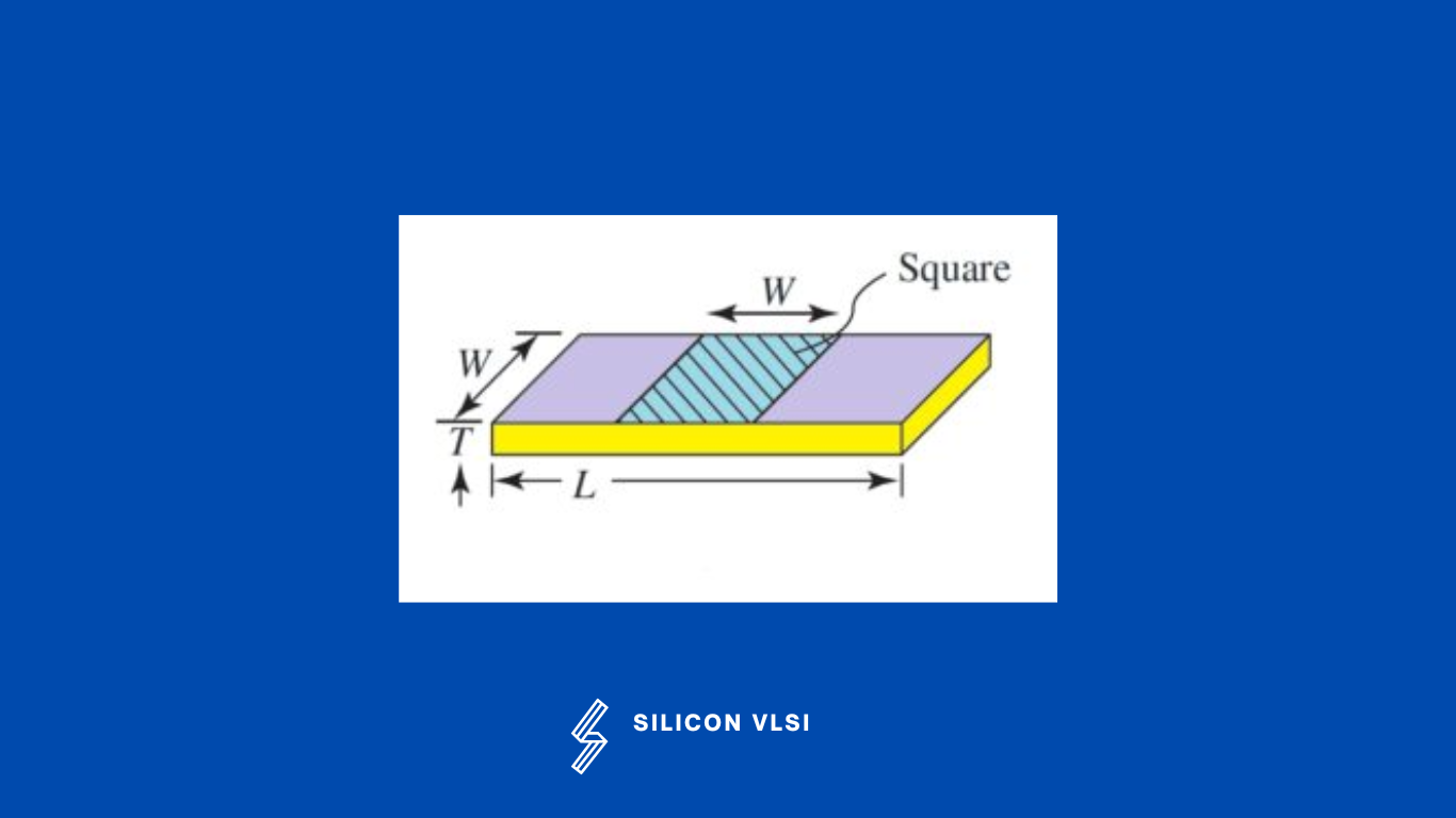
An interconnect wire with a length of L, a width of W, and a thickness of T has a resistance of R given by


[terminal]R = ρL/A= ρL/TW[/terminal]


where ρ is the resistivity of the material of which the wire is made. The quantity ρ/T is called the sheet resistance and has the dimension of ohms, although it is usually expressed as ohms/square.

Where:

For interconnect wires, you’ll need to consider the specific geometry and material properties of the wires you’re working with.

  1. Resistivity (ρ): This is a property of the material the wire is made from. It’s typically provided in ohm-meters (Ω⋅m).
  2. Length (L): Measure the length of the wire along its path.
  3. Cross-Sectional Area (A): The cross-sectional area of the wire can be calculated using the formula for the area of a circle:

What are various types of parasitic effects introduced by interconnects in integrated circuits?

Interconnects in an integrated circuit introduces three types of parasitic effects: capacitive parasitics, resistive parasitics, and inductive parasitics. These parasitic effects have multiple impacts on the circuit’s behavior:

  1. They cause an increase in propagation delay, consequently lowering performance.
  2. They affect energy dissipation and power distribution.
  3. They introduce extra noise sources, influencing the reliability of the circuit.


Interconnect Wire Resistance
Share. Facebook Twitter Pinterest LinkedIn Tumblr Email

Related Posts

How Shielding Avoids Crosstalk Problem? What Exactly Happens There?

September 22, 2024

Navigating the Challenges of Gate Dielectric Scaling in MOS Transistors

August 1, 2024

Challenges in Modern SoC Design Verification

April 20, 2024
Leave A Reply Cancel Reply

Facebook X (Twitter) Instagram Pinterest Vimeo YouTube
  • About Us
  • Contact Us
  • Privacy Policy
© 2025 Siliconvlsi.

Type above and press Enter to search. Press Esc to cancel.