
Voltage
Voltage is the pressure from an electrical circuit’s power source that pushes charged electrons called current through a conducting loop.
Although all of the components in a series circuit have the same amount of current flowing through them, voltage divider circuits are used to generate various voltage levels from a single voltage source.
Because the “Volt,” the voltage unit, measures the magnitude of the potential difference between two places, voltage dividers are sometimes referred to as potential dividers. A voltage or potential divider is a straightforward passive circuit that makes use of the voltage drop that occurs when components are linked in series.
The simplest straightforward example of a voltage divider is a potentiometer, which is a variable resistor with a sliding contact. We can apply a voltage across its terminals and generate an output voltage proportional to the mechanical position of its sliding contact. However, since they are two-terminal devices that can be connected in series, individual resistors, capacitors, and inductors can also be used to create voltage dividers.
Voltage Divider Rule
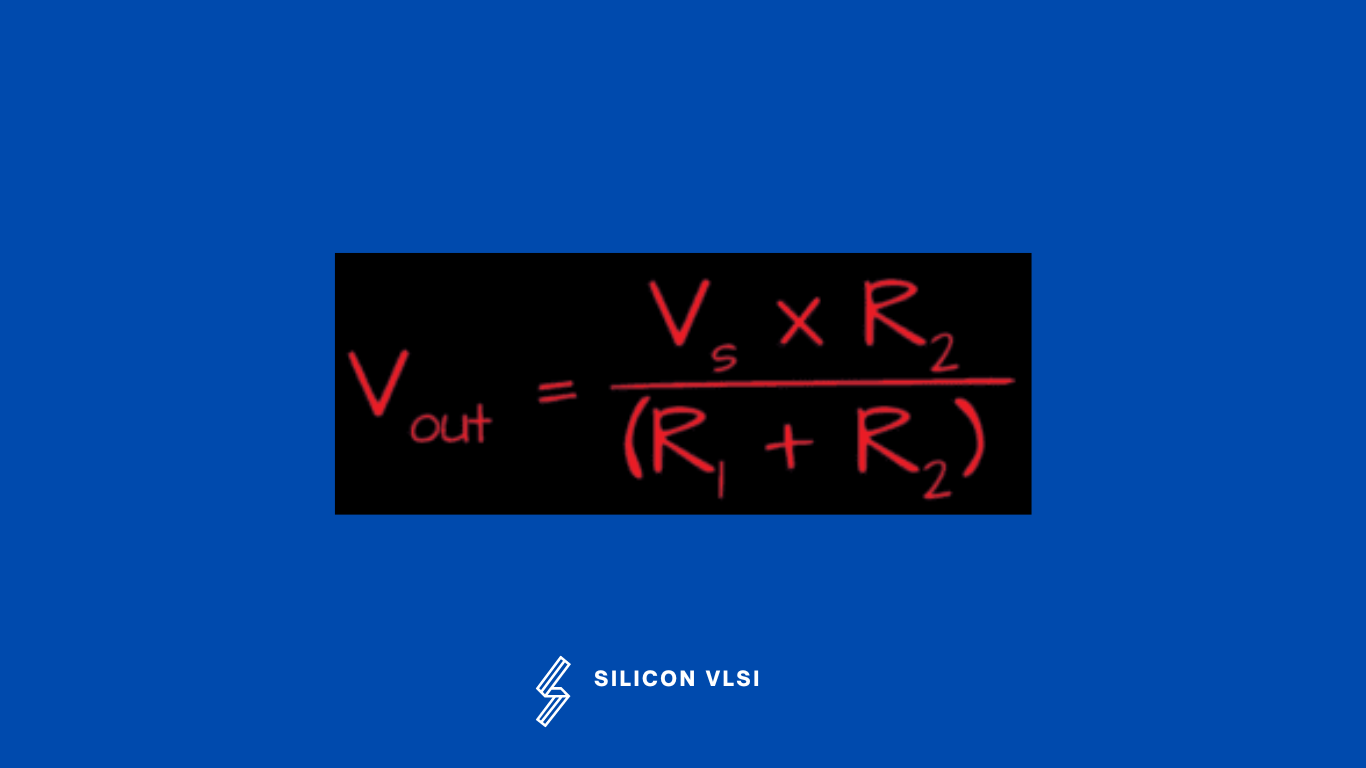
According to the voltage division rule, each resistor receives a proportionate share of the total voltage applied across a series connection of many resistors. This indicates that the voltage loss will be greatest across the resistor with the highest resistance value. For a resistor with the lowest value of resistance, it will also be the minimum. #
In essence, the voltage drop across each resistance in a series-connected resistance is what the voltage division rule informs us of. The AC and DC circuits are both covered by this rule. However, for obvious reasons, impedance value should be taken into account instead of resistance value when applying this rule to an AC circuit.
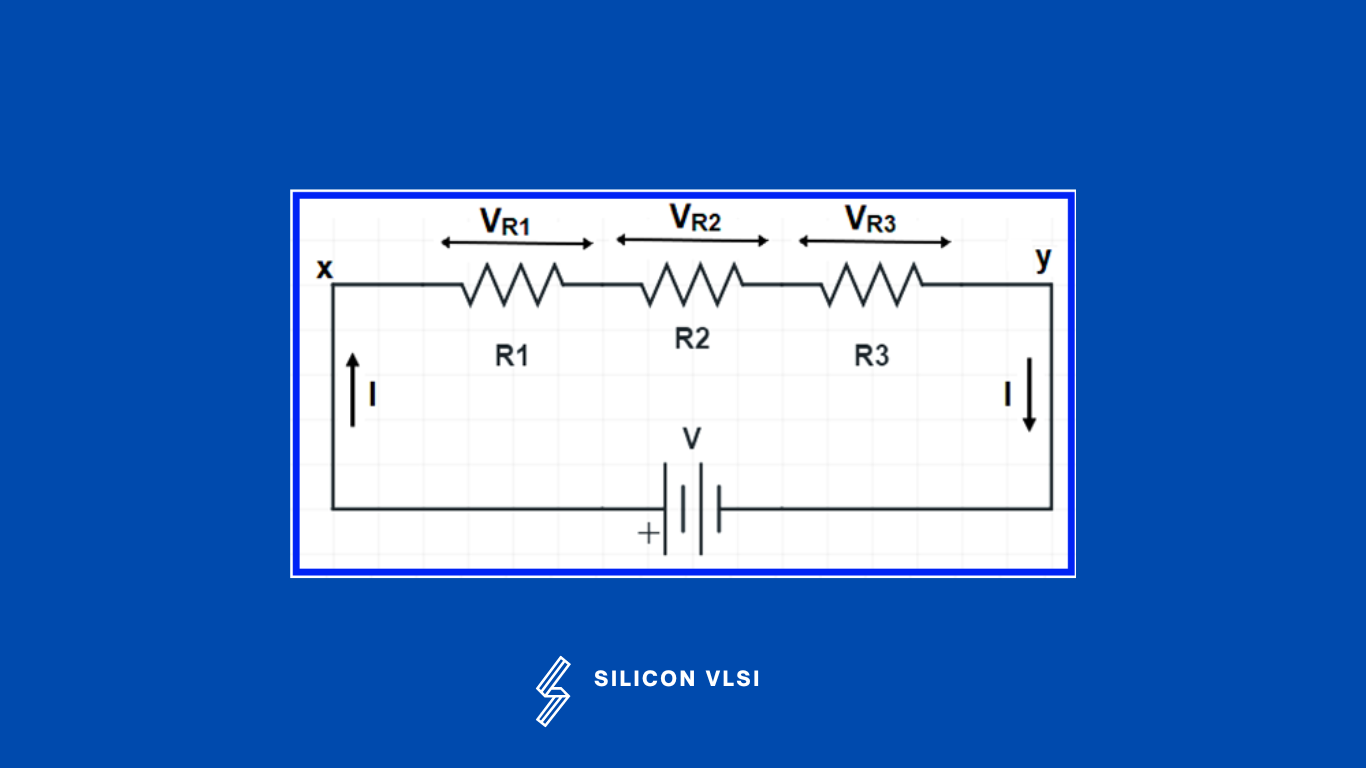
We want to find the voltage drop of each of the resistances. Now let’s assume, VR1, VR2 & VR3 be the voltage drop across resistance R1, R2, and R3 respectively.
we can find the voltage distribution across the individual resistance as shown below.
VR1 = V[ R1 / (R1+ R2+ R3)]

VR2 = V[ R2 / (R1+ R2+ R3)]

VR3 = V[ R3 / (R1+ R2+ R3)]
Resistor in Series
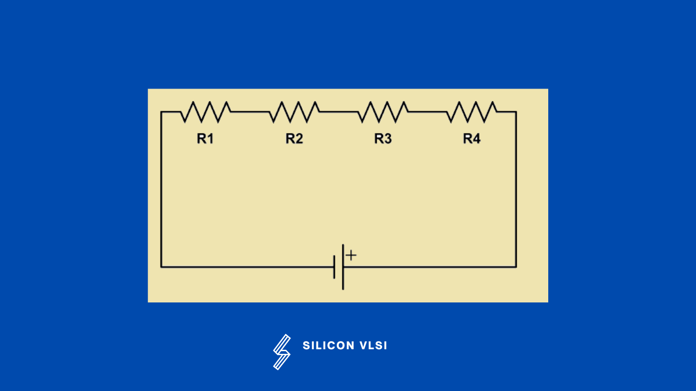
When resistors are connected in series, the total voltage across all the resistors is equal to the sum of the voltages across each resistor. When the same amount of current passes through each resistor at the same time, two or more resistors are said to be linked in series. The voltage across each resistor in such circuits varies. If any resistor in a series connection breaks or has a problem, the circuit as a whole is shut off. A series circuit can be built more easily than a parallel circuit. #
For the below circuit, the total resistance is given as:
Rtotal = R1 + R2 + ….. + Rn
The characteristics of a series circuit of resistors are:
- The same current flows through each of the resistors. #
- Each resistor has its own corresponding voltage drop.
- Voltage drops are additive or the total voltage applied is equal to the sum of voltage dropped in each resistor.
- Powers are additive or the total power consumed by the circuit is the sum of power consumed by each of the resistors
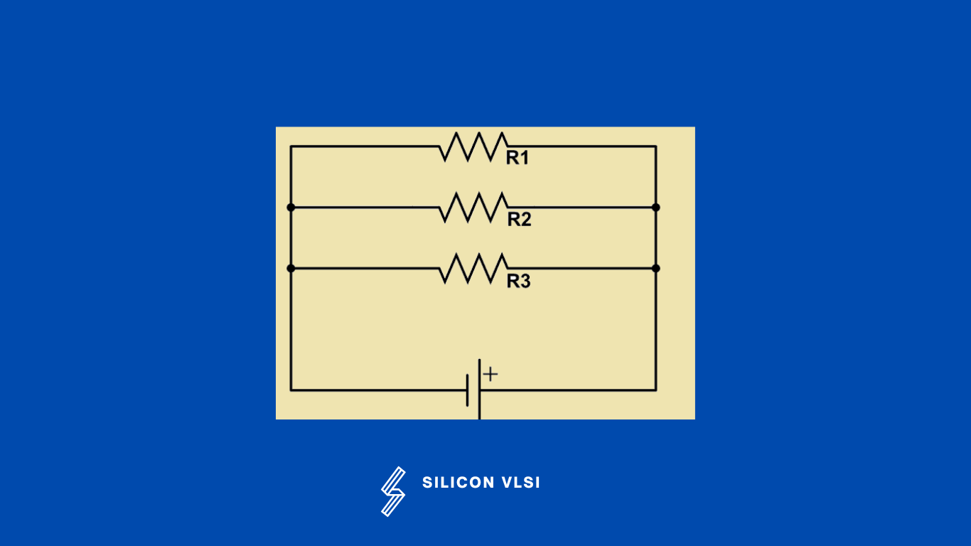
Resistors in Parallel
Resistors are in parallel when their terminals are connected to the same two nodes. The equivalent overall resistance is smaller than the smallest parallel resistor. When the voltage is uniform across all of the resistors, two or more resistors are said to be linked in parallel. When branches in such circuits come together at a common location, the current is split off and then recombined. In a parallel circuit, it is simple to connect or disconnect a resistor or any other component without affecting the other components. #
For the below circuit, the total resistance is given as:
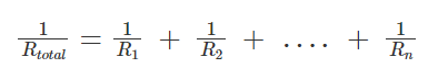
The characteristics of a Parallel circuit of resistors are:
- The same voltage acts across all the resistors. #
- Each resistor has its individual current flowing through them.
- The currents are additive or the total current flowing through the circuit is the sum of the current flowing through each resistor
- Powers are additive or the total power consumed by the circuit is the sum of power consumed by each of the resistors.