What are VIAs in VLSI?
When you need to establish connections between different metal layers in VLSI, you’ll use a poly layer along with the metal layers you want to connect. These connections are called VIAs. In the illustration, you’ll see green metal representing the horizontal layer, blue metal showing the vertical layer, and a yellow-highlighted poly layer positioned between them. Whenever you want to connect the blue and green layers, you’ll rely on this VIA to make the link.
Types of VIAs
There are two primary types of VIAs:
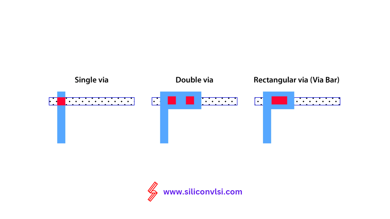
Single Cut VIA
A single-cut VIA consists of only one connection between two metals. The image below provides a clearer visualization.
Multi-Cut VIA(Duble Via)
A multi-cut VIA involves multiple VIA connections between the two metal layers
Rectangular Via
A rectangular via offers less resistance than a single cut via(square via)
It is important to note the advantages offered by multi-cut vias compared to single-cut vias. Let’s explore these advantages in greater detail:
Advantage of Vias
Increased Safety through Multiple Connections
Multi-cut vias provide a higher level of safety due to the presence of multiple connections. If one connection were to fail, the additional connections within the VIA would ensure continuity and preserve the integrity of the overall connection.
Lower Resistance with Parallel Connections
In line with the concept that resistance decreases in parallel connections, multi-cut vias offer the advantage of lower resistance. By establishing multiple connections within the VIA, the overall resistance of the circuit is reduced, resulting in improved signal flow.
In conclusion, VIAs play a important role in facilitating seamless interconnections between different metal layers in VLSI. Understanding the distinction between single-cut and multi-cut vias enables designers to make informed decisions based on their specific project requirements. The advantages offered by multi-cut vias, such as enhanced safety and reduced resistance, underscore their significance in contemporary circuit design. By harnessing the potential of VIAs, VLSI engineers can optimize connectivity and drive the development of innovative electronic systems.