
Cable bonding is essentially how we connect the outer coverings, or sheaths, of two cables electrically. We can make this connection at one end or both ends of the cable, depending on how we intend to use it. Now, let’s talk about why bonding cables is so important!
What is the purpose of bonding?
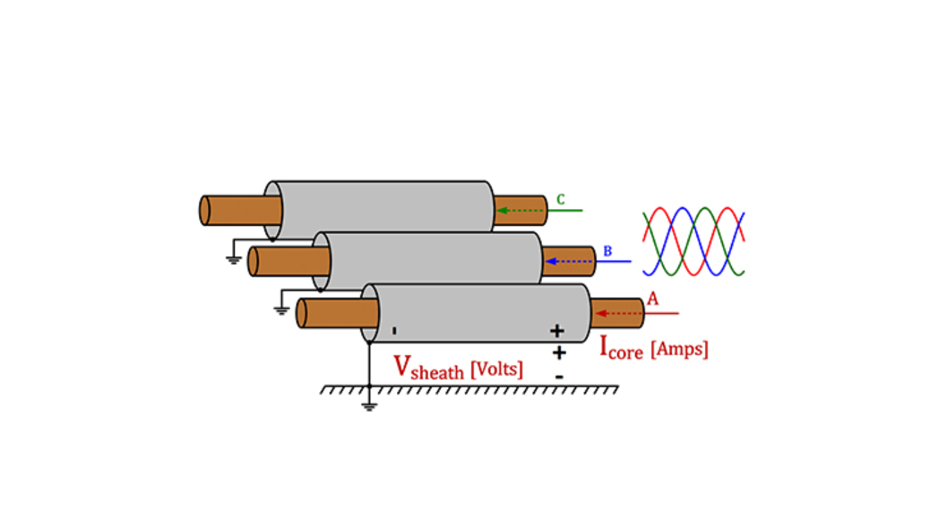
The purpose of cable bonding depends on the situation you are dealing with. In most cases, we use bonding to link conductive parts together, making sure they stay at the same electrical potential. By doing this, you and I can avoid potential differences that might cause safety risks or lead to problems in how equipment works.
Methods of Bonding:
- Single Point Bonding System
- Both End Bonding Systems
- Cross Bonding System
- Both End-bonding systems
Both End Bonding Systems
- The simplest way to prevent voltage issues in the sheath is the End Bonding system.
- It’s easy to ground both ends of the cable sheath, requiring minimal materials and is cost-effective.
- However, circulating current flows through the cable sheath, generating heat, increasing losses, and reducing cable lifespan.
- This system is suitable for short cable sections of up to tens of meters.
Advantages of Single Point Bonding
No circulating current, leading to no heating in the cable screen. Economical.
Disadvantages of Single Point Bonding
The induced voltage at the ungrounded end of the cable.
May need additional equipment like SVL (Sheath Voltage Limiter) during extreme sheath voltage during a fault. An Earth Continuity Conductor is required to handle undesirable fault currents