Close Menu
  • Analog Design
    • Latest Analog Layout Interview Questions (2025)
  • Digital Design
    • Digital Electronics Interview Question(2025)
    • Top VLSI Interview Questions
  • Physical Design
    • Physical Design Interview Questions for VLSI Engineers
  • Verilog
    • Verilog Interview Questions(2024)
  • Forum
Facebook Instagram YouTube LinkedIn WhatsApp
SiliconvlsiSiliconvlsi
Ask Questions Register in Forum Login in Forum
Facebook Instagram YouTube LinkedIn WhatsApp
  • Analog Design
    • Latest Analog Layout Interview Questions (2025)
  • Digital Design
    • Digital Electronics Interview Question(2025)
    • Top VLSI Interview Questions
  • Physical Design
    • Physical Design Interview Questions for VLSI Engineers
  • Verilog
    • Verilog Interview Questions(2024)
  • Forum
SiliconvlsiSiliconvlsi
Home»VLSI Design»What is Poynting’s Vector?
VLSI Design

What is Poynting’s Vector?

siliconvlsiBy siliconvlsiJanuary 1, 2024No Comments2 Mins Read
Facebook Pinterest LinkedIn Email WhatsApp
Share
Facebook Twitter LinkedIn Pinterest Email

POYNTING’S VECTOR

The transfer of energy between two conductors necessitates the presence of both a magnetic (H) and an electric (E) field. The H field corresponds to current flow, while the E field relates to the voltage across the lines. Throughout the space between conductors, the E-field direction is always perpendicular to the H-field direction, and both are perpendicular to the transmission path. The product of E X H at any point in space is known as Poynting’s vector, pointing in the direction of energy flow. E is measured in volts per meter, and H is measured in amperes per meter, resulting in watts per meter squared at a specific point in space.

Poynting’s vector
Poynting’s vector

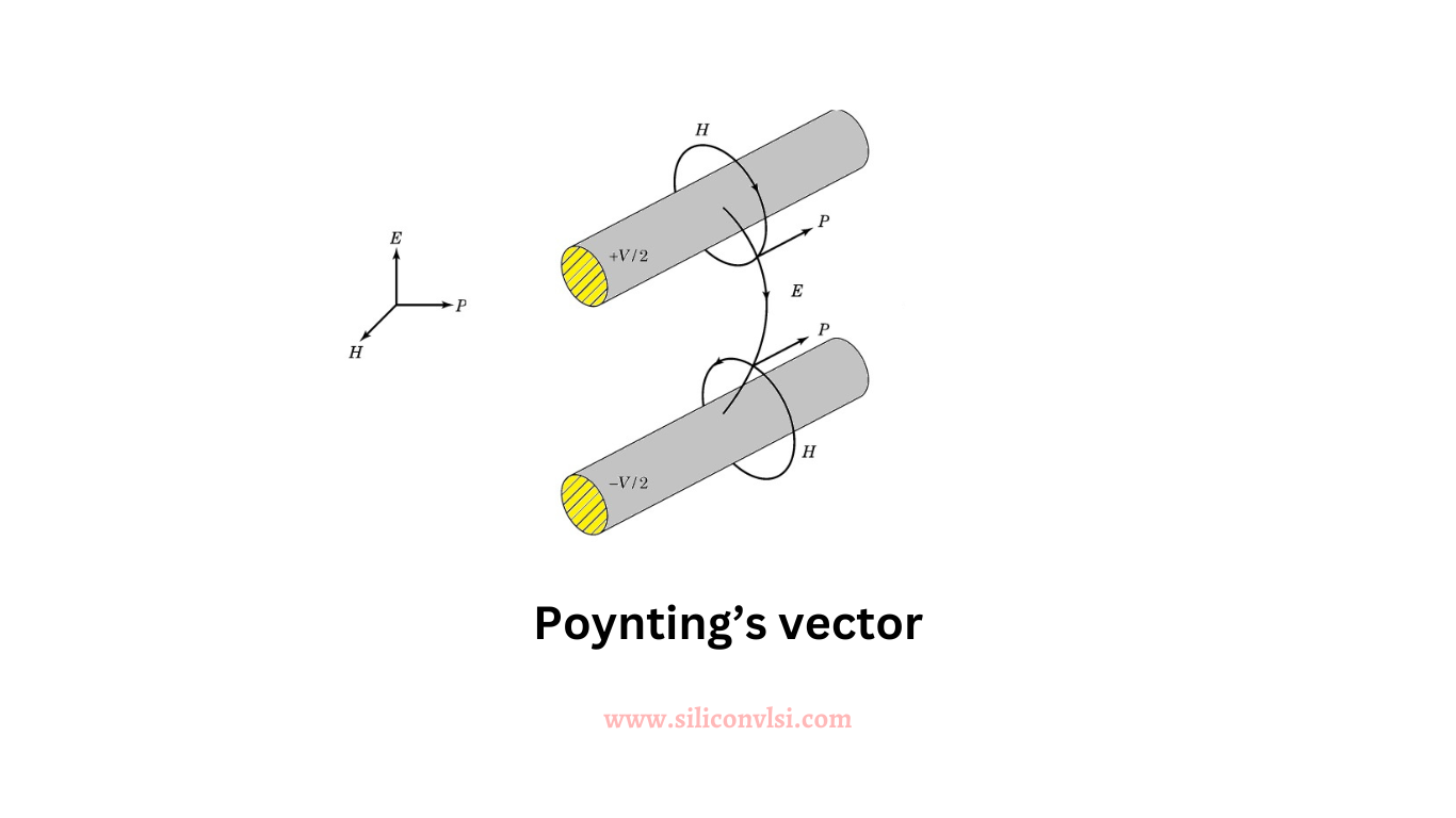
Consider a plane cutting perpendicular to the transmission line, as illustrated in Figure 1. Divide the plane into small regions with constant E and H values. Multiply these values by the area in each region and sum the results over the entire plane. The outcome is the power supplied by the battery, aligning with the circuit-based approach of volts multiplied by current.

What is the Right-Hand Rule?

Practically, the right-hand rule is employed by pointing the first two fingers and thumb at right angles to each other. The first two fingers represent the E- and H-field direction, respectively, while the thumb points in the direction of energy flow. If the E field is reversed, the hand must turn over, and the thumb points in the opposite direction, indicating the reversal of energy flow.

Share. Facebook Twitter Pinterest LinkedIn Tumblr Email

Related Posts

How Shielding Avoids Crosstalk Problem? What Exactly Happens There?

September 22, 2024

Navigating the Challenges of Gate Dielectric Scaling in MOS Transistors

August 1, 2024

Challenges in Modern SoC Design Verification

April 20, 2024
Leave A Reply Cancel Reply

Facebook X (Twitter) Instagram Pinterest Vimeo YouTube
  • About Us
  • Contact Us
  • Privacy Policy
© 2025 Siliconvlsi.

Type above and press Enter to search. Press Esc to cancel.