
ESD Clamp Circuit in VLSI
Clamps are known as static ESD clamps. A diode, MOSFET, and SCR-based clamps are known as static ESD clamps.ESD Clamps can be divided into two categories: static and transient.
Static clamps
Current and voltage responses are static or steady-state with static clamps. Static clamps are activated by a fixed voltage level. The clamp will conduct current as long as the voltage is higher than this value. Static ESD clamps are made of diodes, MOSFETs, or SCRs.The static clamp typically occupies less space and is composed of fewer elements. If a static clamp falsely triggers while power is applied to the part, it will result in a large, steady current and may lead to damage.
Transient clamps
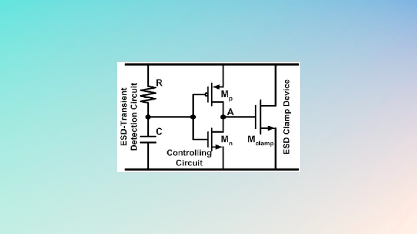
The quick variations in voltage and/or current that accompany an ESD incident are exploited by transient clamps. An element turns on quickly and then slowly during this transient. When triggered, this sort of clamp operates for a predetermined period of time. The time constant is determined by an RC network. The supply lines’ extremely quick events frequently cause these clamps to open.
Transient clamps can be designed to turn on very quickly and handle larger transient events. The disadvantage is that they will also respond to any fast event, even noise. And if they falsely trigger while the part is powered, they could interfere with circuit operation and it is likely that the part will be destroyed.
Working Function of ESD Clamp Circuit.
Electrostatic discharge can harm electronic devices, hence an ESD clamp circuit is used to prevent this from happening. The device’s power supply lines are commonly connected in parallel with a diode and a transient voltage suppressor (TVS).
A low-resistance channel for the ESD current is provided by the diode, and a “clamp” is created by the TVS by restricting the voltage on the power supply lines to a safe level. The diode and TVS cooperate during an ESD event to swiftly direct the ESD current away from the device, protecting its delicate components. In the Above Circuit, When the ESD event occurs, Capacitor C will be short, and hence Inverter will turn on, hence Big NMOS(Mclamp) will be one, so all currents will be discharged.