

ESD in VLSI: 7 Essential Protection Concepts Explained
Electrostatic Discharge (ESD) is the sudden transfer of electrical charge between two objects that are at different electrical potentials. In an integrated circuit, an ESD event can generate a very high voltage and a large, short-duration current pulse.
Because MOSFET gate oxides are extremely thin in modern technologies, an uncontrolled ESD event can cause permanent damage to the device. Therefore, ESD protection is an essential part of IC design.
What Is ESD in VLSI?
ESD in VLSI refers to the protection techniques and circuits used to protect an integrated circuit from electrostatic discharge events.
An ESD event can occur when:
- A charged human body contacts an IC pin.
- A charged device contacts another object.
- Two objects at different potentials come into contact.
- A strong electric field causes charge transfer between nearby structures.
An ESD event is usually very short, but it can produce a large peak current and high voltage.
Without an appropriate protection structure, this energy can damage:
- Gate oxide
- Junctions
- Metal interconnects
- Contacts and vias
- Transistor structures
Why Is ESD Protection Important in CMOS?
CMOS circuits use MOSFETs with very thin dielectric layers.
The electric field across an oxide can be approximated by:
Eox ≈ Vox / tox
where:
- Eox = electric field across the oxide
- Vox = voltage across the oxide
- tox = oxide thickness
Therefore, for a given voltage:
Smaller tox → Larger electric field
This is one reason why thin-oxide devices require careful ESD protection.
An excessive electric field can cause dielectric degradation or breakdown.
Why Are Thick-Oxide Devices Used for ESD Protection?
A common ESD-design approach uses devices that can withstand substantially higher electrical stress than the thin-oxide core devices.
A thick-oxide device can provide greater voltage tolerance because its oxide is thicker than the core transistor’s gate dielectric.
However, the ESD protection structure is not simply selected based on oxide thickness.
Its:
- Device structure
- Breakdown behavior
- Layout
- Current-handling capability
- Triggering characteristics
- Parasitic elements
must also be carefully engineered.
The objective is to provide a controlled path that safely conducts the ESD current while protecting sensitive core circuitry.
How Does an ESD Protection Circuit Work?
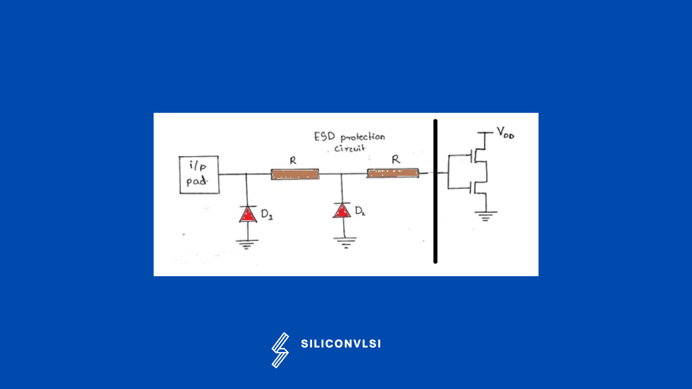
An IC input is normally not connected directly to a sensitive thin-oxide gate without protection.
Instead, an ESD protection network is placed between the external pad and the internal circuitry.
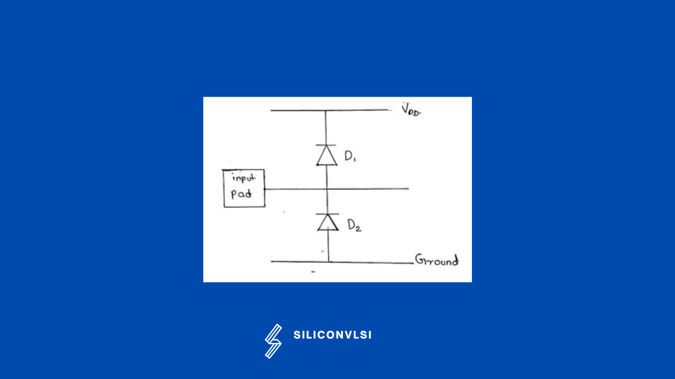
A simplified protection concept uses paths toward the power and ground rails.
The protection circuit should remain essentially inactive during normal operation while providing a low-impedance or controlled discharge path during an ESD event.
The basic idea is:
ESD event → protection device activates → ESD current is diverted → internal device is protected
ESD Protection During Normal Operation
During normal operation, the protection elements should not significantly interfere with the input signal.
For a simplified diode-based protection structure:
- The upper protection path is normally reverse-biased for ordinary input voltages.
- The lower protection path is also normally reverse-biased.
- The internal circuit therefore operates normally.
The exact bias condition depends on the particular ESD topology.
What Happens When Input Voltage Exceeds the Supply?
Suppose an input pad experiences a voltage significantly above the positive supply rail.
The upper protection device can become forward-biased or otherwise triggered, depending on the protection architecture.
The resulting current is directed toward the appropriate power rail instead of allowing the full stress voltage to reach the sensitive core transistor.
Conceptually:
High positive ESD pulse → upper protection path conducts → current diverted to VDD
The internal gate is therefore protected from the majority of the ESD stress.
What Happens When Input Voltage Goes Below Ground?
Now consider a large negative voltage applied to the input pad.
The lower protection path can conduct and provide a route toward ground.
Conceptually:
Negative ESD pulse → lower protection path conducts → current diverted toward VSS/GND
Again, the objective is to prevent the sensitive internal circuitry from experiencing the full ESD voltage.
What Happens During a Severe ESD Event?
An ESD event can involve a very rapid voltage and current transient.
Depending on the protection architecture, the protection device may operate through mechanisms such as:
- Forward conduction
- Avalanche breakdown
- Snapback
- Controlled MOSFET conduction
- Silicon-controlled rectifier (SCR) action
The protection device must be capable of carrying the ESD current without failing before the protected circuit.
This is why ESD layout is as important as the circuit topology.
ESD Protection and MOSFET Gate Oxide
The gate oxide is particularly sensitive to high electric fields.
Consider two cases:
Normal operation
Small voltage across thin oxide → acceptable electric field
ESD event
Large voltage across thin oxide → potentially destructive electric field
If the oxide experiences excessive stress, it can suffer:
- Permanent dielectric damage
- Increased gate leakage
- Localized breakdown
- Complete oxide failure
An ESD protection network therefore limits the voltage that reaches the sensitive internal gate.
ESD Protection in Input, Output and Power Pins
ESD protection is not limited to input pins.
Protection is commonly required for:
Input Pins
Protect internal input gates from external electrostatic events.
Output Pins
Protect output-driver transistors and internal circuitry from externally applied ESD stress.
Power Pins
Provide appropriate discharge paths between supply rails and ground during an ESD event.
The exact protection architecture depends on the pin type and the required ESD specifications.
Why ESD Layout Is Important
A protection circuit can have the correct schematic and still fail if its physical layout is poorly designed.
During an ESD event, the protection structure may need to conduct a large transient current.
The layout therefore needs to provide:
- Low-resistance current paths
- Adequate metal width
- Appropriate contacts and vias
- Uniform current distribution
- Sufficient spacing
- Robust device structures
- Good connection to power and ground
Parasitic resistance and inductance can also affect the transient voltage seen by the protected circuitry.
ESD vs Normal Circuit Operation
| Characteristic | Normal Operation | ESD Event |
|---|---|---|
| Voltage | Within specified operating range | Can be very high |
| Current | Normal circuit current | Large transient current |
| Duration | Continuous or normal switching | Very short pulse |
| Protection circuit | Mostly inactive | Activated/conducting |
| Objective | Normal circuit operation | Safely discharge stored charge |
| Risk | Normal electrical stress | Device damage |
What Is the Purpose of ESD Protection?
The primary purpose of ESD protection is to prevent an electrostatic event from damaging the IC.
A good ESD protection system should:
- Remain sufficiently inactive during normal operation.
- Detect or respond to an ESD transient.
- Provide a safe discharge path.
- Limit the voltage reaching sensitive circuitry.
- Carry the required ESD current.
- Survive the event without permanent damage.
- Meet the applicable ESD reliability requirements.
The protection system therefore has to balance protection strength with normal circuit performance.
ESD Protection Trade-Offs
Adding a protection device is not completely free from side effects.
An input protection network can introduce:
- Additional capacitance
- Leakage
- Area overhead
- Parasitic resistance
- Signal delay
For high-speed interfaces, excessive input capacitance can reduce signal performance.
Therefore, ESD design requires a balance between:
Strong ESD protection ↔ Low parasitic loading
ESD Protection in Modern VLSI
As semiconductor technology scales, the challenge becomes more difficult because device dimensions and dielectric thicknesses become smaller.
At the same time, modern circuits often operate with lower supply voltages and have increasingly stringent performance requirements.
Consequently, ESD protection must be carefully co-designed with:
- I/O circuits
- Core devices
- Power distribution
- Package connections
- Physical layout
- Reliability requirements
The protection approach is highly dependent on the semiconductor process.
Common ESD Protection Techniques
Several ESD protection structures are used in semiconductor technologies.
Diode-Based Protection
Diodes can provide discharge paths from an I/O pad toward the supply rails.
MOS-Based Protection
Specially designed MOS structures can be used to conduct ESD current.
SCR-Based Protection
SCR structures can provide very strong current-handling capability and are widely studied for robust ESD protection.
RC-Triggered Protection
Some power-rail protection circuits use RC-triggered structures to activate an ESD discharge path during a fast transient.
The appropriate solution depends on the process technology and ESD requirements.
Common Misconceptions About ESD
“ESD only happens when a person touches a chip.”
Not necessarily.
ESD can occur through several charge-transfer mechanisms, including contact and field-induced events.
“The thin gate oxide is protected simply because the supply voltage is low.”
No.
An ESD pulse is a transient event and can produce voltages far beyond the normal operating range.
“A diode always breaks down during ESD.”
Not necessarily.
Some protection structures conduct through forward bias, while others use avalanche, snapback, SCR action, or other mechanisms.
“Only the input pin needs ESD protection.”
No.
Input, output, power, and other externally accessible interfaces may require protection depending on the IC architecture.
Frequently Asked Questions
What is ESD in VLSI?
ESD in VLSI refers to the design and implementation of protection structures that protect integrated circuits from electrostatic discharge events.
Why is ESD dangerous for MOSFETs?
An ESD event can produce a large transient voltage and current. The resulting electrical stress can damage thin gate dielectrics, junctions, contacts, metal interconnects, and other device structures.
Why is a thick-oxide device useful for ESD protection?
A thick-oxide structure can provide greater voltage tolerance than a thin-oxide core device, making it suitable for certain high-voltage protection structures. The complete protection behavior also depends on the device architecture and layout.
What happens when the input voltage exceeds VDD?
In a simplified diode-clamp architecture, the upper protection path conducts and diverts the excessive positive current toward the supply rail.
What happens when the input voltage goes below ground?
The lower protection path can conduct and divert the negative ESD current toward the ground rail.
Why is ESD layout important?
ESD events can produce large transient currents. The protection layout must provide sufficiently robust and low-impedance current paths while avoiding localized current crowding and excessive device stress.
Key Takeaways
- ESD stands for Electrostatic Discharge.
- ESD is a rapid transfer of electrical charge between objects at different potentials.
- ESD events can generate very high voltage and large transient currents.
- Thin MOS gate dielectrics are particularly vulnerable to excessive electric-field stress.
- ESD protection diverts dangerous transient energy away from sensitive internal circuitry.
- Protection structures can use diode conduction, avalanche, snapback, MOS-based structures, SCRs, and other mechanisms.
- Input, output, and power interfaces can all require ESD protection.
- ESD layout is critical because protection devices must safely carry large transient currents.
- Stronger protection can introduce capacitance, leakage, and area overhead.
- Modern ESD protection requires careful coordination between device design, circuit design, layout, packaging, and reliability.