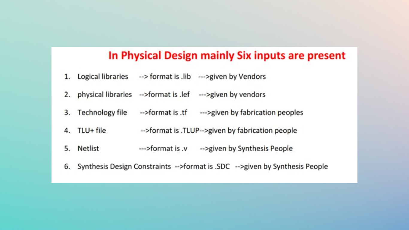
The intended use or purpose of the product or structure, ergonomics and human factors, materials, and manufacturing methods, as well as any applicable codes and regulations, can all be considered physical design inputs. Additionally, during the physical design phase, variables like cost, sustainability, and aesthetics may be taken into account.
Gate-level Netlist
Format= .v
Given by the Synthesis team.
It is a synthesized and optimized netlist that contains information on all the logical connections of the standard cells and macros.
It has cell info, net info, and pin/port information.
Physical library
File format = .lef(Cadence), FRAM(Synopsys).
Liberty Exchange Format (LEF)
Given by Vendor.
It contains all the physical information of all the standard cells and macros.
Info such as – shape, size, symmetry, and orientation of the cells is present.
Pin information like- pin names, direction, shape, antenna related info is also defined.
Technology file
Format = .techlef (Cadence), .tf(Synopsys).
Given by Foundry.
It contains technology node info.
It has unit info (Ex: ns).
Tech file is written in ASCII format.
It contains all the metal layer info like – shape, color, width, pitch, area, spacing between metal layers, base layer info, resistance (per sq. unit).
TLU+ file
Format = .tlup
Given by Fab team.
It has RC parasitic info per unit length of the metal.
RC values are used to calculate the net delay.
Either a .tlup file or a .itf file is used.
Logical library
Format = .lib, .db
Given by Vendor.
It contains functional and timing information of all the cells.
Timing details such as cell delays, setup time, and hold time.
Design rules – max capacitance, max transition, and max fanout are defined.
It also has PVT(Process Voltage Temperature) parameters.
Cell delays are checked from the lookup table.
SDC: Standard Design Constraints
Format = .sdc
Given by the Synthesis team.
This contains all the timing constraints.
Constraints – Clock definitions, input delay, output delay, clock latency, clock uncertainty.
Exceptions – Mutlicycle path, false path, disable timing arc, and half cycle path details are described.
A few other files are also used
MMMC:- Multi-Mode Multi-Corner file
It is used to generate different analysis views based on different delay corners and constraint modes.
UPF:- Unified Power Format
This file is used when a single chip uses multiple voltages.

![]()