

Difference Between CMOS and TTL
TTL (Transistor-Transistor Logic) and CMOS (Complementary Metal-Oxide-Semiconductor) are two important digital logic families. Both are used to implement logic gates and digital circuits, but they differ significantly in power consumption, switching behavior, noise immunity, voltage range, and practical applications.
The CMOS vs TTL comparison is especially important when learning digital electronics because it explains why CMOS became dominant in modern low-power digital systems, while TTL played a major role in earlier digital electronics.
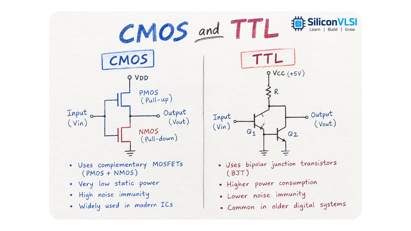
What Is CMOS?
CMOS stands for Complementary Metal-Oxide-Semiconductor. CMOS logic uses complementary PMOS and NMOS transistors to implement digital logic functions.
In a typical CMOS gate, the PMOS network helps pull the output toward the supply voltage, while the NMOS network helps pull the output toward ground.
One of the biggest advantages of CMOS is its very low static power consumption when the circuit is not switching. This makes CMOS particularly suitable for modern processors, memory, microcontrollers, ASICs, and other low-power VLSI circuits.
What Is TTL?
TTL stands for Transistor-Transistor Logic. TTL logic circuits primarily use bipolar junction transistors (BJTs) to implement digital logic functions.
TTL was widely used in earlier generations of digital systems because it provided good switching performance and reliable logic operation. Classic TTL families typically operate around a 5 V supply, although different TTL subfamilies have different electrical characteristics.
Compared with conventional CMOS logic, TTL generally consumes more power, particularly because bipolar circuits draw more current during operation.
CMOS vs TTL: Key Differences
| Feature | CMOS | TTL |
|---|---|---|
| Full Form | Complementary Metal-Oxide-Semiconductor | Transistor-Transistor Logic |
| Main Device | MOSFETs | Bipolar Junction Transistors |
| Power Consumption | Generally lower, especially for static CMOS | Generally higher |
| Static Power | Very low in conventional CMOS | Higher than conventional CMOS |
| Switching Speed | Depends strongly on the CMOS generation and technology | Classic TTL is relatively fast for its era |
| Noise Immunity | Generally high because of wider logic voltage margins | Generally lower than CMOS for comparable logic families |
| Input Impedance | Very high | Relatively low |
| Input Capacitance | Can be significant | Generally lower than MOS inputs |
| Fan-Out | Often high, but limited by capacitance and timing | Limited mainly by input/output current requirements |
| Supply Voltage | Available across many voltage ranges depending on the family | Traditionally centered around 5 V |
| ESD Sensitivity | MOS inputs can be sensitive to ESD | Generally less sensitive at the input structure level |
| Common Applications | Modern digital ICs, processors, memories, VLSI | Older digital systems and legacy logic circuits |
1. Power Consumption
Power consumption is one of the most important differences between CMOS and TTL.
Conventional CMOS has extremely low static power consumption because, in a stable logic state, ideally one transistor network is conducting while the other is off. Real CMOS circuits still consume leakage power, especially in modern technologies.
During switching, CMOS consumes dynamic power approximately according to:
Pdynamic ≈ α × C × VDD² × f
where:
- α = switching activity
- C = effective switched capacitance
- VDD = supply voltage
- f = switching frequency
TTL generally consumes more power because its bipolar transistor circuits require current during normal operation.
Therefore, CMOS is usually preferred when low power and high integration density are important.
2. Switching Speed
Switching speed depends on the particular logic family and technology, so it is not accurate to say that TTL is always faster than CMOS.
Classic TTL families were known for good switching speed compared with the CMOS technologies available at the time. However, modern CMOS technologies can operate at extremely high frequencies and are used in high-speed processors, memory, communication circuits, and other advanced ICs.
Therefore, when comparing CMOS and TTL, the specific logic family, process technology, load capacitance, and operating conditions should be considered.
3. Noise Immunity
CMOS generally provides good noise immunity because its logic levels can have relatively wide noise margins.
Noise margin describes how much unwanted voltage disturbance a digital signal can tolerate before it is incorrectly interpreted as a logic 0 or logic 1.
Higher noise margin can improve reliable operation when signals are affected by electrical interference.
However, noise immunity is also dependent on the particular CMOS or TTL family and its specified input/output voltage levels.
4. Input Impedance
CMOS inputs are connected to MOSFET gates, which ideally draw almost no DC current.
Therefore, CMOS has very high input impedance.
TTL inputs, on the other hand, use bipolar transistor structures and generally draw more input current.
This difference affects how much current one logic gate must supply to drive another gate.
5. Fan-Out
Fan-out is the number of digital inputs that one logic output can reliably drive while meeting the required voltage and timing specifications.
CMOS inputs have very low DC input current, so a CMOS output can often drive many CMOS inputs. However, every input adds capacitance, so excessive fan-out can increase propagation delay and dynamic power.
TTL fan-out is more directly affected by the input and output current requirements of the bipolar circuits.
Therefore, fan-out should be evaluated using the electrical specifications of the particular logic family, rather than assuming CMOS always has unlimited fan-out.
6. Supply Voltage and Logic Compatibility
Traditional TTL logic is strongly associated with a 5 V supply and has defined input and output voltage specifications around that supply.
CMOS logic has been manufactured for a much wider range of supply voltages. Modern CMOS devices may operate at significantly lower voltages, depending on the technology and device family.
This makes CMOS especially useful in modern systems where reducing supply voltage helps reduce dynamic power.
When connecting CMOS and TTL devices together, designers must check:
- Input HIGH and LOW voltage limits
- Output HIGH and LOW voltage levels
- Input and output current requirements
- Supply voltage
- Timing specifications
Simply connecting two logic families because they both represent binary 0 and 1 is not sufficient.
7. Applications
CMOS is now the dominant technology for a large portion of modern digital IC design.
Typical CMOS applications include:
- Microprocessors
- Microcontrollers
- SRAM and other memory circuits
- ASICs
- Digital signal processors
- System-on-Chip (SoC) designs
- Mobile and battery-powered electronics
- Modern VLSI circuits
TTL is mainly encountered in legacy systems, educational circuits, older equipment, and applications where compatibility with existing TTL logic is required.
CMOS vs TTL: Advantages and Disadvantages
| CMOS | TTL |
|---|---|
| Very low static power | Higher power consumption |
| High input impedance | Lower input impedance |
| Good noise margins | Good switching performance in classic families |
| Supports many supply-voltage families | Traditionally associated with 5 V operation |
| Very high integration density | Historically important for SSI/MSI digital systems |
| Can be sensitive to ESD | Generally less sensitive to MOS-gate ESD damage |
| Dynamic power increases with switching frequency | Significant operating power even when not switching |
Which Is Better: CMOS or TTL?
There is no universal answer because the correct choice depends on the application.
For modern VLSI and low-power digital systems, CMOS is generally the preferred technology because of its low static power, high integration density, and availability across many supply-voltage ranges.
TTL remains important when working with legacy equipment, existing TTL designs, or systems specifically designed around TTL electrical characteristics.
CMOS vs TTL: Quick Comparison
The easiest way to remember the difference is:
CMOS → Low power, high input impedance, modern VLSI
TTL → Bipolar logic, higher power, historically important 5 V logic
However, switching speed, fan-out, noise immunity, and voltage compatibility should always be compared using the specifications of the specific logic families, rather than making a blanket statement about all CMOS or all TTL devices.
Frequently Asked Questions
Is CMOS faster than TTL?
Modern CMOS can be extremely fast and is used in high-speed digital systems. Classic TTL families were faster than the CMOS technologies available when they were introduced. Therefore, the answer depends on the specific technology and logic family.
Why does CMOS consume less power than TTL?
Conventional CMOS has very low static current because ideally there is no direct DC path from the supply to ground in a stable logic state. Most CMOS power is associated with switching and leakage.
Which has better noise immunity, CMOS or TTL?
CMOS generally provides good noise margins, but the exact noise immunity depends on the particular logic family and its specified voltage levels.
Can CMOS and TTL be connected directly?
Not always. Their voltage and current specifications can differ, so compatibility must be checked before connecting them directly.
Is TTL still used today?
Yes. Although CMOS dominates modern digital ICs, TTL and TTL-compatible logic remain relevant in legacy systems, educational hardware, and applications requiring compatibility with existing designs.
Conclusion
The CMOS vs TTL comparison shows why CMOS became the dominant logic technology in modern digital electronics. CMOS offers low static power consumption, high input impedance, high integration density, and support for many low-voltage technologies.
TTL was extremely important in the development of digital electronics and remains relevant in legacy and TTL-compatible systems.
For VLSI design, understanding the differences between these two logic families provides a useful foundation for learning CMOS logic, power consumption, noise margins, digital circuit design, and semiconductor technology.